Take a graph sheet and divide it into 4 equal parts. Mark origin at the center of the graph sheet. Now mark +ve X-axis as Vf, -ve X-axis as Vr, +ve Y-axis as Ifand –ve Y-axis as Ir. Mark the readings tabulated for Si forward biased condition in first Quadrant and Si reverse biased condition in third Quadrant.
Take a graph sheet and divide it into 4 equal parts. Mark origin at the center of the graph sheet. Now mark +ve X-axis as Vf, -ve X-axis as Vr, +ve Y-axis as Ifand –ve Y-axis as Ir. Mark the readings tabulated for Si forward biased condition in first Quadrant and Si reverse biased condition in third Quadrant.

Electricity for Refrigeration, Heating, and Air Conditioning (MindTap Course List)
10th Edition
ISBN:9781337399128
Author:Russell E. Smith
Publisher:Russell E. Smith
Chapter5: Components, Symbols, And Circuitry Of Air-conditioning Wiring Diagrams
Section: Chapter Questions
Problem 16RQ: Which of the following is not a requirement for an electric circuit? a. a source b. a path c. a load...

Related questions
Question
Graph:
- Take a graph sheet and divide it into 4 equal parts. Mark origin at the center of the graph sheet.
- Now mark +ve X-axis as Vf, -ve X-axis as Vr, +ve Y-axis as Ifand –ve Y-axis as Ir.
- Mark the readings tabulated for Si forward biased condition in first Quadrant and Si reverse biased condition in third Quadrant.
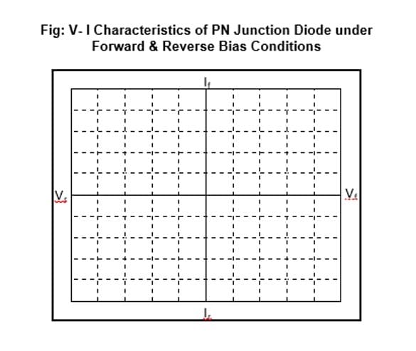
Transcribed Image Text:Fig: V-I Characteristics of PN Junction Diode under
Forward & Reverse Bias Conditions
V.
Ve
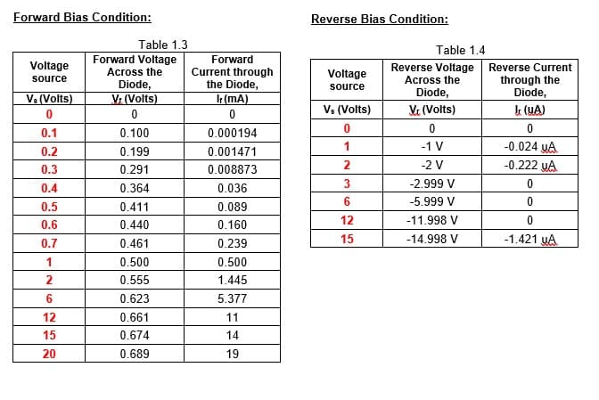
Transcribed Image Text:Forward Bias Condition:
Reverse Bias Condition:
Table 1.3
Forward Voltage
Across the
Diode,
Vr (Volts)
Table 1.4
Forward
Reverse Voltage Reverse Current
Across the
Diode,
Voltage
Current through
the Diode,
Voltage
through the
Diode,
source
source
Ve (Volts)
(mA)
Va (Volts)
Ve (Volts)
k (YA)
0.1
0.100
0.000194
-0.024 yA
-0.222 uA
0.2
0.199
0.001471
1
-1 V
2
-2 V
0.3
0.291
0.008873
-2.999 V
0.4
0.364
0.036
6.
-5.999 V
0.5
0.411
0.089
12
-11.998 V
0.6
0.440
0.160
0.7
0.461
0.239
15
-14.998 V
-1.421 UA
1
0.500
0.500
2
0.555
1.445
6
0.623
5.377
12
0.661
11
15
0.674
14
20
0.689
19
Expert Solution
This question has been solved!
Explore an expertly crafted, step-by-step solution for a thorough understanding of key concepts.

Step by step
Solved in 2 steps with 1 images

Knowledge Booster


Learn more about
Need a deep-dive on the concept behind this application? Look no further. Learn more about this topic, electrical-engineering and related others by exploring similar questions and additional content below.Recommended textbooks for you
Electricity for Refrigeration, Heating, and Air C…
Mechanical Engineering
ISBN:
9781337399128
Author:
Russell E. Smith
Publisher:
Cengage Learning
Electricity for Refrigeration, Heating, and Air C…
Mechanical Engineering
ISBN:
9781337399128
Author:
Russell E. Smith
Publisher:
Cengage Learning