that has three different positions: a, b, and N. Initially, the switch is in position N (the circuit is open). After the circuit switch is moved to position a and time At elapses, the current in the circuit reaches 50% of its maximum value. The switch remains in position a for the time interval 107. After that, the switch is moved into position b. (a) What is the time constant of this RL circuit? (b) What are the values of the electric current in the circuit, the energy density in the coil, and the emf across the coil (i) when the switch has been at position a for a long time? after the switch has moved to position b and T seconds have elapsed? (ii) after the switch has moved to position b and 37 seconds have elapsed? Support your answers with a graph of the electric cur- rent in the circuit versus time. (iii) N S R 000
that has three different positions: a, b, and N. Initially, the switch is in position N (the circuit is open). After the circuit switch is moved to position a and time At elapses, the current in the circuit reaches 50% of its maximum value. The switch remains in position a for the time interval 107. After that, the switch is moved into position b. (a) What is the time constant of this RL circuit? (b) What are the values of the electric current in the circuit, the energy density in the coil, and the emf across the coil (i) when the switch has been at position a for a long time? after the switch has moved to position b and T seconds have elapsed? (ii) after the switch has moved to position b and 37 seconds have elapsed? Support your answers with a graph of the electric cur- rent in the circuit versus time. (iii) N S R 000

Delmar's Standard Textbook Of Electricity
7th Edition
ISBN:9781337900348
Author:Stephen L. Herman
Publisher:Stephen L. Herman
Chapter24: Resistive-inductive-capacitive Parallel Circuits
Section: Chapter Questions
Problem 1PP: The circuit in Figure 24-2 is connected to a 120-V, 60-Hz line. The resistor has a resistance of 36...

Related questions
Question
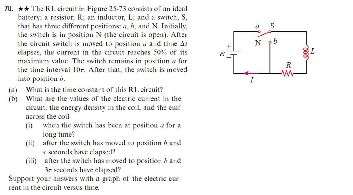
Transcribed Image Text:70. ★★ The RL circuit in Figure 25-73 consists of an ideal
battery; a resistor, R; an inductor, L; and a switch, S,
that has three different positions: a, b, and N. Initially,
the switch is in position N (the circuit is open). After
the circuit switch is moved to position a and time At
elapses, the current in the circuit reaches 50% of its
maximum value. The switch remains in position a for
the time interval 107. After that, the switch is moved
into position b.
(a) What is the time constant of this RL circuit?
(b) What are the values of the electric current in the
circuit, the energy density in the coil, and the emf
across the coil
(i)
(ii)
(iii)
when the switch has been at position a for a
long time?
after the switch has moved to position b and
T seconds have elapsed?
after the switch has moved to position b and
37 seconds have elapsed?
Support your answers with a graph of the electric cur-
rent in the circuit versus time.
a S
N ob
R
gL
Expert Solution
This question has been solved!
Explore an expertly crafted, step-by-step solution for a thorough understanding of key concepts.

Step by step
Solved in 7 steps with 7 images

Knowledge Booster


Learn more about
Need a deep-dive on the concept behind this application? Look no further. Learn more about this topic, electrical-engineering and related others by exploring similar questions and additional content below.Recommended textbooks for you
Delmar's Standard Textbook Of Electricity
Electrical Engineering
ISBN:
9781337900348
Author:
Stephen L. Herman
Publisher:
Cengage Learning

Electricity for Refrigeration, Heating, and Air C…
Mechanical Engineering
ISBN:
9781337399128
Author:
Russell E. Smith
Publisher:
Cengage Learning
Delmar's Standard Textbook Of Electricity
Electrical Engineering
ISBN:
9781337900348
Author:
Stephen L. Herman
Publisher:
Cengage Learning
Electricity for Refrigeration, Heating, and Air C…
Mechanical Engineering
ISBN:
9781337399128
Author:
Russell E. Smith
Publisher:
Cengage Learning