The ASM chart shown in Figure 4 specifies a synchronous sequential logic circuit. Derive a suitable state table from the ASM and design the circuit for the state table using JK flip-flop and logic gates.
The ASM chart shown in Figure 4 specifies a synchronous sequential logic circuit. Derive a suitable state table from the ASM and design the circuit for the state table using JK flip-flop and logic gates.

Chapter28: Overcurrent Protection–fuses And Circuit Breakers
Section: Chapter Questions
Problem 11R: State four possible combinations of service equipment that meet the requirements of 110.9 and 110.10...

Related questions
Question
The ASM chart shown in Figure 4 specifies a synchronous sequential logic circuit. Derive a suitable state table from the ASM and design the circuit for the state table using JK flip-flop and logic gates.
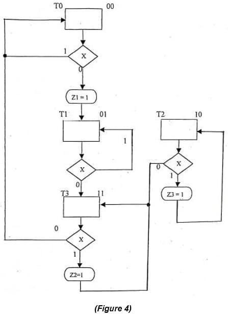
Transcribed Image Text:TO
00
ZI = 1
T1
01
T2
10
1
T3
Z3 = 1
Z2=1
(Figure 4)
1.
Expert Solution
This question has been solved!
Explore an expertly crafted, step-by-step solution for a thorough understanding of key concepts.

Step by step
Solved in 5 steps with 7 images

Knowledge Booster


Learn more about
Need a deep-dive on the concept behind this application? Look no further. Learn more about this topic, electrical-engineering and related others by exploring similar questions and additional content below.Recommended textbooks for you
EBK ELECTRICAL WIRING RESIDENTIAL
Electrical Engineering
ISBN:
9781337516549
Author:
Simmons
Publisher:
CENGAGE LEARNING - CONSIGNMENT
EBK ELECTRICAL WIRING RESIDENTIAL
Electrical Engineering
ISBN:
9781337516549
Author:
Simmons
Publisher:
CENGAGE LEARNING - CONSIGNMENT