the balanond three phase paralel cireuit belew.complete the tables uing the provided values Assuming sa sequence strietly une stered values throughout the computationa. Provide up to fur decimal places Note: Neglect watmeter range mtipller
the balanond three phase paralel cireuit belew.complete the tables uing the provided values Assuming sa sequence strietly une stered values throughout the computationa. Provide up to fur decimal places Note: Neglect watmeter range mtipller

Power System Analysis and Design (MindTap Course List)
6th Edition
ISBN:9781305632134
Author:J. Duncan Glover, Thomas Overbye, Mulukutla S. Sarma
Publisher:J. Duncan Glover, Thomas Overbye, Mulukutla S. Sarma
Chapter2: Fundamentals
Section: Chapter Questions
Problem 2.45P: Two balanced Y-connected loads, one drawing 10 kW at 0.8 power factor lagging and the other IS kW at...

Related questions
Question
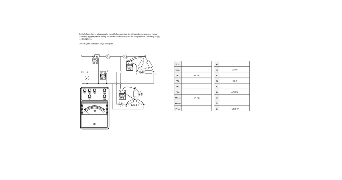
Transcribed Image Text:In the balanced three-phase parallel circuit below, complete the tables using the provided values.
Assuming b-c-a sequence, strictly use stored values throughout the computations. Provide up to four
decimal places.
Note: Neglect wattmeter range multiplier
Ao
A2
W1
V1
Load 1
АЗ
W3
V2
230-V
во
W1
350-W
A1
(V1
W2
W2
A2
0.8-A
W3
A3
W4
A4
0.51798
SA
120V
W4
0.6 lag
PFLoad1
Ozı
240V
A4
PFLoad2
Ozz
Load 2
PFTotal
+18.1949°
Expert Solution
This question has been solved!
Explore an expertly crafted, step-by-step solution for a thorough understanding of key concepts.

Step by step
Solved in 5 steps with 5 images

Knowledge Booster


Learn more about
Need a deep-dive on the concept behind this application? Look no further. Learn more about this topic, electrical-engineering and related others by exploring similar questions and additional content below.Recommended textbooks for you
Power System Analysis and Design (MindTap Course …
Electrical Engineering
ISBN:
9781305632134
Author:
J. Duncan Glover, Thomas Overbye, Mulukutla S. Sarma
Publisher:
Cengage Learning
Power System Analysis and Design (MindTap Course …
Electrical Engineering
ISBN:
9781305632134
Author:
J. Duncan Glover, Thomas Overbye, Mulukutla S. Sarma
Publisher:
Cengage Learning