The circuit shown in Figure 3 consists of an inductor L, a capacitor C, and a resistor R. The input is the source voltage Vs(t) and the output is the voltage Vo across the resistor Ro. Vs(t) R Figure 3 Using IL and Vc as the state variables, Construct a complete state-space model for the system shown in figure 3. Specifically, express system equations in the vector-matrix form: i = Ax+ Bu y = Cx+Du in the usual notation, where 'x' is the state vector, 'u' is the input vector, and 'y' is the output vector, and determine all the elements of the four matrices A, B, C, and D in terms of the circuit parameters R, Ro, L, and C.
The circuit shown in Figure 3 consists of an inductor L, a capacitor C, and a resistor R. The input is the source voltage Vs(t) and the output is the voltage Vo across the resistor Ro. Vs(t) R Figure 3 Using IL and Vc as the state variables, Construct a complete state-space model for the system shown in figure 3. Specifically, express system equations in the vector-matrix form: i = Ax+ Bu y = Cx+Du in the usual notation, where 'x' is the state vector, 'u' is the input vector, and 'y' is the output vector, and determine all the elements of the four matrices A, B, C, and D in terms of the circuit parameters R, Ro, L, and C.

Power System Analysis and Design (MindTap Course List)
6th Edition
ISBN:9781305632134
Author:J. Duncan Glover, Thomas Overbye, Mulukutla S. Sarma
Publisher:J. Duncan Glover, Thomas Overbye, Mulukutla S. Sarma
Chapter6: Power Flows
Section: Chapter Questions
Problem 6.59P

Related questions
Question
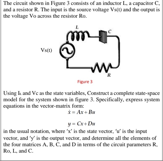
The circuit shown in Figure 3 consists of an inductor L, a capacitor C,
and a resistor R. The input is the source voltage Vs(t) and the output is
the voltage Vo across the resistor Ro.
Using IL and Vc as the state variables, Construct a complete state-space
model for the system shown in figure 3. Specifically, express system
equations in the vector -matrix form:
in the usual notation, where ‘x’ is the state vector, ‘u’ is the input
vector, and ‘y’ is the output vector, and determine all the elements of
the four matrices A, B, C, and D in terms of the circuit parameters R,
Ro, L, and C.
Transcribed Image Text:The circuit shown in Figure 3 consists of an inductor L, a capacitor C,
and a resistor R. The input is the source voltage Vs(t) and the output is
the voltage Vo across the resistor Ro.
Vs(t)
R
Figure 3
Using IL and Vc as the state variables, Construct a complete state-space
model for the system shown in figure 3. Specifically, express system
equations in the vector-matrix form:
i = Ax+ Bu
y = Cx+Du
in the usual notation, where 'x' is the state vector, 'u' is the input
vector, and 'y' is the output vector, and determine all the elements of
the four matrices A, B, C, and D in terms of the circuit parameters R,
Ro, L, and C.
Expert Solution
This question has been solved!
Explore an expertly crafted, step-by-step solution for a thorough understanding of key concepts.

Step by step
Solved in 2 steps with 2 images

Knowledge Booster


Learn more about
Need a deep-dive on the concept behind this application? Look no further. Learn more about this topic, electrical-engineering and related others by exploring similar questions and additional content below.Recommended textbooks for you
Power System Analysis and Design (MindTap Course …
Electrical Engineering
ISBN:
9781305632134
Author:
J. Duncan Glover, Thomas Overbye, Mulukutla S. Sarma
Publisher:
Cengage Learning
Power System Analysis and Design (MindTap Course …
Electrical Engineering
ISBN:
9781305632134
Author:
J. Duncan Glover, Thomas Overbye, Mulukutla S. Sarma
Publisher:
Cengage Learning