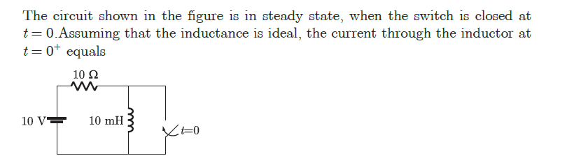
The circuit shown in the figure is in steady state, when the switch is closed at t= 0.Assuming that the inductance is ideal, the current through the inductor at t=0* equals 10 Ω 10 V= 10 mH =0
The circuit shown in the figure is in steady state, when the switch is closed at t= 0.Assuming that the inductance is ideal, the current through the inductor at t=0* equals 10 Ω 10 V= 10 mH =0

Delmar's Standard Textbook Of Electricity
7th Edition
ISBN:9781337900348
Author:Stephen L. Herman
Publisher:Stephen L. Herman
Chapter24: Resistive-inductive-capacitive Parallel Circuits
Section: Chapter Questions
Problem 1RQ: An AC circuit contains a 24 resistor, a 15.9-mH inductor, and a 13.3F capacitor connected in...

Related questions

Question
Transcribed Image Text:The circuit shown in the figure is in steady state, when the switch is closed at
t= 0.Assuming that the inductance is ideal, the current through the inductor at
t= 0+ equals
10 Ω
10 V
10 mH
Expert Solution
This question has been solved!
Explore an expertly crafted, step-by-step solution for a thorough understanding of key concepts.

Step by step
Solved in 3 steps with 2 images

Knowledge Booster


Learn more about
Need a deep-dive on the concept behind this application? Look no further. Learn more about this topic, electrical-engineering and related others by exploring similar questions and additional content below.Recommended textbooks for you
Delmar's Standard Textbook Of Electricity
Electrical Engineering
ISBN:
9781337900348
Author:
Stephen L. Herman
Publisher:
Cengage Learning
Delmar's Standard Textbook Of Electricity
Electrical Engineering
ISBN:
9781337900348
Author:
Stephen L. Herman
Publisher:
Cengage Learning