The diagram shown is that of a L1 Pressure switch Manual pushbutton 120 VAC Temperature switch L2 OL M • Motor starter coil
The diagram shown is that of a L1 Pressure switch Manual pushbutton 120 VAC Temperature switch L2 OL M • Motor starter coil

Delmar's Standard Textbook Of Electricity
7th Edition
ISBN:9781337900348
Author:Stephen L. Herman
Publisher:Stephen L. Herman
Chapter13: Magnetic Induction
Section: Chapter Questions
Problem 1PA

Related questions

Question
Transcribed Image Text:D
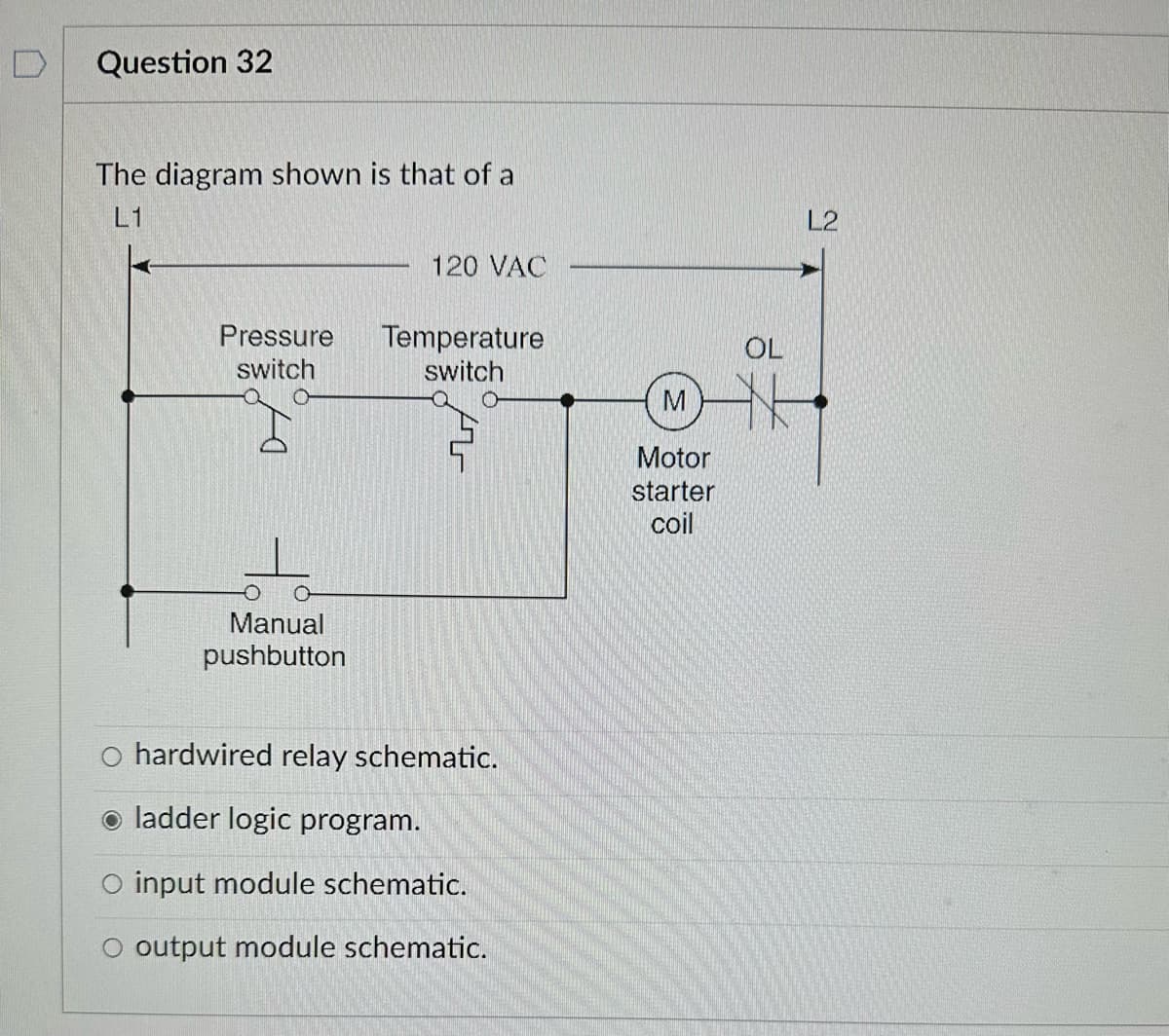
Question 32
The diagram shown is that of a
L1
Pressure
switch
Manual
pushbutton
120 VAC
Temperature
switch
O hardwired relay schematic.
ladder logic program.
O input module schematic.
O output module schematic.
M
Motor
starter
coil
OL
L2
Expert Solution
This question has been solved!
Explore an expertly crafted, step-by-step solution for a thorough understanding of key concepts.

This is a popular solution!

Trending now
This is a popular solution!

Step by step
Solved in 2 steps

Knowledge Booster


Learn more about
Need a deep-dive on the concept behind this application? Look no further. Learn more about this topic, electrical-engineering and related others by exploring similar questions and additional content below.Recommended textbooks for you
Delmar's Standard Textbook Of Electricity
Electrical Engineering
ISBN:
9781337900348
Author:
Stephen L. Herman
Publisher:
Cengage Learning
Delmar's Standard Textbook Of Electricity
Electrical Engineering
ISBN:
9781337900348
Author:
Stephen L. Herman
Publisher:
Cengage Learning