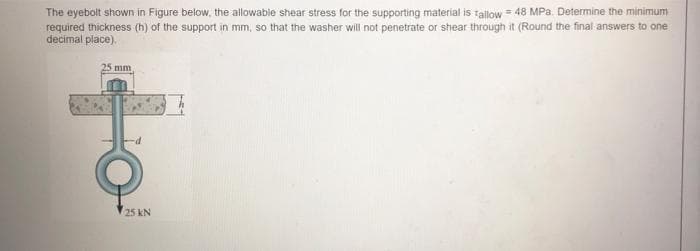
The eyebolt shown in Figure below, the allowable shear stress for the supporting material is Tallow = 48 MPa. Determine the minimum required thickness (h) of the support in mm, so that the washer will not penetrate or shear through it (Round the final answers to one decimal place).


Q: The cross-sectional area shown is subjected to V = 600 kN and M =1000 kN-m. What is the transverse…
A:
Q: The rectangular bar is connected to the support bracket with a circular pin, as shown in the figure.…
A:
Q: 1- A sheet-metal blank is to be bent as shown in Figure. The metal has a modulus of elasticity = 205…
A:
Q: Four pulleys are attached to the 50-mm-diameter aluminum shaft. If torques are applied to the…
A:
Q: The cylinder is shown in Figure is made of steel having a specific weightof gst = 490 lb>ft3.…
A:
Q: a) If a pipe with an inner diameter of 36 mm is subjected to an axial load of 5.20 x 10⁵ N and the…
A: a) Given: Inner diameter=36mm or 0.036mAxial load (F)=5.2×10⁵NMaximum allowable stress…
Q: A certain point in the mechanical part has shearing and normal stresses measured in MN/m^2 as shown…
A: Write the given data.
Q: For the state of plane stress shown in Figure-1. below; a) Draw Mohr's circle, b) Find the maximum…
A: Given Data: The stress in the x-direction is, σx=-20 MPa. The stress in the y-direction is, σy=90…
Q: 1.25 The piece of wood, 100 mm by 100 mm in cross section, contains a glued joint inclined at the…
A: Given data: The area of a cross section of wood, A = 100 mm by 100 mm. The stress for tension, σt =…
Q: 450 kN and 100 kN forces were applied to the recessed beam shown in the figure. Find the stresses at…
A:
Q: Homework :-in the figure shown. Find the total deformation and the stress in each section if E is…
A:
Q: given figure, 40 kN 60 KN determine the .D normal stress + 2m - Sm Sm in MPa at segment AB.…
A:
Q: The rectangular piece of wood, 51 mm by 183 mm, is used as a compression block. The grain of the…
A:
Q: 90 MPA 60 MPA 20 MPA
A: Given that, σx=-20 MPa,σy=90 MPa,τxy=60 MPa, Steps to draw mohr's circle: 1. Take direct stress at…
Q: 1. In the figure shown, determine the diameter of the rod C if the allowable stress 86.60 MPa.…
A:
Q: A clevis-type pipe hanger supports an 8-in.-diameter pipe, as shown in Figure. The hanger rod has a…
A: Given data: W=2000 lb Need to determine the normal stress in the hanger rod, shear stress in the…
Q: 1) For the data given below, calculate the minimum value of the thickness of the object in the…
A: Given: The maximum allowed normal stress = 400 MPa The maximum allowed shear stress = 240 MPa The…
Q: Consider the figure below. If T1=3,500 lbs and T2 = 2,500lbs, fin the angle alpha made by T2 from…
A: Given data: Tension T1=3500 lbs Tension T2=2500 lbs
Q: B) The Figure shows Mohr's circle for a point in a physical object that is subjected to plane…
A:
Q: For the punching operation shown in the figure, compute the shear stress (in GPa) in the material if…
A: GivenP=5500kNt=1.5mm=0.0015md=15mm=0.015mL=20mm=0.020m
Q: The steel tie-bar shown in the figure has been designed to carry a tension force of 103 kN when…
A: The maximum bearing stress at A: 110.0 MPa.
Q: An aluminum rod is rigidly attached between a steel rod and a bronze rod as shown in the figure.…
A: Consider the Free Body Diagram: Force acting on Bronze rod:FCD=2PStress in Bronze…
Q: The assembly in Figure below consists of a light rigid bar AB, pinned at O, that is attached to the…
A: Given:AB=0.75mOB=1.5m∆=5mmFor steelAst=250mm2E=200 GPaFor aluminiumL=BC=2mAal=300mm2E=70 GPaTo find…
Q: A rod is composed of three segments as shown and carries the axial loads P1=120 kN and P2=50 kN as…
A:
Q: Plane Stress In the stress element given in Figure 3, WITH MOHR CIRCLE; (a) Determine the principal…
A: Mohr circle is a two dimensional graphical method of expressing the normal stresses and shear stress…
Q: The state of stress at a point, for a body in place stress, is shown in the figure below. If the…
A:
Q: For question 103A and 103B, the thin-walled cylindrical container shown below. Say p is the internal…
A: Internal pressure P=15 MPa Inside diameter d=20 mm Wall thickness t=10 mm Longitudinal stress in a…
Q: 1. As shown in the figure, three wires with different areas and modulus of elasticity are used to…
A: When wires are drawn, they tend to extend in the longitudinal direction. This elongation depends on…
Q: piece of wood, 84 mm by 180 mm, is used as a compression block. The grain of the wood makes a 21.2º…
A:
Q: For the stress state shown in the figure below, use the Mohr’s circle method to determine (a) the…
A: This is a case of pure shear,therefore, Radius of the mohr circle…
Q: 1.24 The figure shows a glued joint, known as a finger joint, in a 6-in. by 3/4-in. piece of lumber.…
A: Given Data: The longitudinal force subjected to the timber is, P=800 lb. The width of the lumber…
Q: Question 2 a) Figure Q2a shows a hollow tube of rectangular cross-section subjected to an axial…
A:
Q: If a pipe with an inner diameter of 36 mm is subjected to an axial load of 5.20 x 10⁵ N and the…
A: given data dia (d) = 36mm load = 5.20 * 105 N presure (P) = 5.20×10⁵π4×0.0362 allowable stress = σ…
Q: Internal pressure and axial tensile force are applied to an open cylindrical tank 605 mm in diameter…
A:
Q: Oy Ot Txy Tnt Ox On (b) (a) On the surface of a structural member, stresses are given as ox=61 MPa,…
A: Given data: Stresses on the surface of structural member σx=61 Mpa σy=32.7 Mpa τxy=-28.1 Mpa α=54.8°…
Q: A wood pole of solid circular cross section (d = diameter) is subjected to a triangular distributed…
A: Calculated minimum required diameter bashed upon allowable bending stress and allowable shear…
Q: The figure shows a bar with a point load of 22 kN applied at the free end, the other end of the bar…
A: Given data: F=22 kNd=6 mm Need to determine the shear stress in the bolt.
Q: b) An aluminium rod is attached between a steel rod and a bronze rod as shown in Figure- 3. The…
A: Given data: The area of steel bar is As=550 mm2 The area of Aluminium bar is Aal=400 mm2 The area of…
Q: . Given the following data of the figure shown : P= 5.5 KN, L, = L, =L, = 2.5 m Strut BC = 100 mm…
A:
Q: A clevis-type pipe hanger supports an 8-in.-diameter pipe, as shown in Figure. The hanger rod has a…
A: Given data: W=2000 lb Need to determine the normal stress in the hanger rod, the shear stress in the…
Q: A 2.4 diameter steel molding is lifted by 4 steel cables as shown. The mold weighs 3 kN/m. (a) what…
A: Given data
Q: A rectangular plate (0 =23°) is formed by welding two triangular plates shown in figure. The plate…
A: GIVEN: σx=-2.3 MPa σy=13 MPa θ=23° TO FIND: The normal stress and Shear stress on the weld plane.
Q: A 30 mm square is drawn on the rim of a large steel pressure vessel. The biaxial stress situation in…
A: First calculate the strain in y-direction εy using the equation. εy=σyE-νσxE Here,σx is the normal…
Q: 1) For the state of stress shown in figure, use the Mohr's circle method to determine (a) The…
A:
Q: A block of with edge lengths 8.30 m. 3.20 m, 4.50 m sits on top of a pillar with a square cross…
A: Solution is attached below: Density = 2.278 g/cm3
Q: 10 MPa 9. Using Mohr's circle, for the figure at the right, determine: a) The angle to the principal…
A: As per our guidelines we are supposed to solve only one question if multiple questions are asked .…
Q: (1) Given: b₁ B P=28 KN Square Bars b₁ = 57 mm P (2) Q =9 kN b2 C b₂ = 19mm (3) Q R = 38kN ↑ D b3 =…
A:
Q: 1. (20 p.) In the figure below, a built-in bar of length L 600 mm is forced by a force that makes…
A:
Q: The two wooden boards shown in Figure are connected by a 0.5-in.-diameter bolt. Washers are…
A:
Q: a) Figure Q2a shows a hollow tube of rectangular cross-section subjected to an axial compressive…
A:

Step by step
Solved in 2 steps with 2 images

- Solve the preceding problem if F =90 mm, F = 42 kN, and t = 40°MPaA spherical balloon is filled with a gas. The outer diameter of the balloon is 20 in. and the thickness is 0,012 in. Calculate the maximum permissible pressure in the balloon if the allowable tensile stress and the allowable shear stress in the balloon are 1 ksi and 0.3 ksi, respectively.A tie-down on the deck of a sailboat consists of a bent bar boiled at both ends, as shown in the figure. The diameter dBof the bar is 1/4 in., the diameter D Wof the washers is 7/8 in., and the thickness is of the fiberglass deck is 3/8 in. If the allowable shear stress in the fiberglass is 300 psi, and the allowable bearing pressure between the washer and the fiberglass is 550 psi, what is the allowable load P allowon the tie-down?
- Solve the preceding problem for an element in plane stress on the bottom surface of a fuel tanker (figure part a); stresses are sx= 105 MPa, sy. = 75 MPa, and ??xy= 25 MPa. Determine the stresses acting on an element oriented at an angle ?? = 40° from the x axis, where the angle is positive when counterclockwise. Show these stresses on a sketch of an element oriented at the angle ??.Two bars AC and BC of the same material support a vertical load P (see figure). The length L of the horizontal bar is fixed, but the angle fl can be varied by moving support A vertically and changing the length of bar AC to correspond with the new position of support A. The allowable stresses in the bars are the same in tension and compression. When the angle ft is reduced, bar AC becomes shorter, but the cross-sectional areas of both bars increase because the axial forces are larger. The opposite effects occur if the angle 0 is increased. Thus, the weight of the structure (which is proportional to the volume) depends upon the angle ft. Determine the angle ft so that the structure has minimum weight without exceeding the allowable stresses in the bars. Note: The weights of the bars are very small compared to the force P and may be disregarded.-26 A rectangular plate of dimensions 125 mm × 75 mm is subjected to tensile stress sy= 67 kPa and compressive stress a. If it is known that the normal stress along the diagonal t—t is ??t= -6.57 kPa, find stress ??y on element A. a
- A steel punch consists of two shafts: upper shaft and lower shaft. Assume that the upper shaft has a diameter d1= 24 mm and the bottom shaft has a diameter d2= 16 mm. The punch is used to insert a hole in a 4 mm plate, as shown in the figure. If a force P - 70 kN is required to create the hole, what is the average shear stress in the plate and the average compressive stress in the upper and lower shaft of the punch?Two boards are joined by gluing along a scarf joint, as shown in the figure. For purposes of cutting and gluing, the angle a between the plane of the joint and the faces of the boards must be between 10° and 40f. Under a tensile load P, the normal stress in the boards is 4.9 MPa. (a) What axe the normal and shear stresses acting on the glued joint if a = 20°? (b) If the allowable shear stress on the joint is 2.25 MPa. what is the largest permissible value of the angle ct? (c) For what angle a with the shear stress on the glued joint be numerically equal to twice the normal stress on the joint?The polyethylene liner of a settling pond is subjected to stresses ax= 350 psi. a = 112 psi. and = -120 psi, as shown by the plalte-stress element in the figure part a. Determine the normal and shear stresses acting on a seam oriented at an angle 01300 to the element, as shown in the figure part b. Show these stresses on a sketch of an element having its sides parallel and perpendicular to the seam.
- The hollow drill pipe for an oil well (sec figure) is 6,2 in. in outer diameter and 0.75 in. in thickness. Just above the bit, the compressive force in the pipe (due to the weight of the pipe) is 62 kips and the torque (due to drilling) is 185 kip-in. Determine the maximum tensile, compressive, and shear stresses in the drill pipe.Solve the preceding problem for a plate of dimensions 100 mm × 250 mm subjected to a compressive stress of 2.5 MPa in the long direction and a tensile stress of 12.0 MPa in the short direction (see figure).An element on the top surface of the fuel tanker in Problem 7.2-1 is in biaxial stress and is subjected to stresses a = -48 MPa and ay = 19 MPa, as shown in the figure. Using Mohr’s circle, determine the following. (a) The stresses acting on an clement oriented at a counterclockwise angle ?? = 25° from the x axis. (b) The maximum shear stresses and associated normal stresses. Show all results on sketches of properly oriented elements.