The figure represents the equivalent circuit of a single-phase transformer, if after doing the respective tests the following values have been obtained: R1 = R'2 = 0.08 Q X1 = X'2 = 0.2 Q Re = 1000 Q; Xm = 400 Q. It is supplied to the load Z' at 240 V, 6 kVA, with a power factor of 0.85 lagging at nominal voltage. Assuming the output voltage as reference to V'2 = 240 / 0°. Calculate: a) The voltage V1 b) current 1 c) the input power factor.
The figure represents the equivalent circuit of a single-phase transformer, if after doing the respective tests the following values have been obtained: R1 = R'2 = 0.08 Q X1 = X'2 = 0.2 Q Re = 1000 Q; Xm = 400 Q. It is supplied to the load Z' at 240 V, 6 kVA, with a power factor of 0.85 lagging at nominal voltage. Assuming the output voltage as reference to V'2 = 240 / 0°. Calculate: a) The voltage V1 b) current 1 c) the input power factor.

Power System Analysis and Design (MindTap Course List)
6th Edition
ISBN:9781305632134
Author:J. Duncan Glover, Thomas Overbye, Mulukutla S. Sarma
Publisher:J. Duncan Glover, Thomas Overbye, Mulukutla S. Sarma
Chapter3: Power Transformers
Section: Chapter Questions
Problem 3.4P: A single-phase 100-kVA,2400/240-volt,60-Hz distribution transformer is used as a step-down...

Related questions

Question
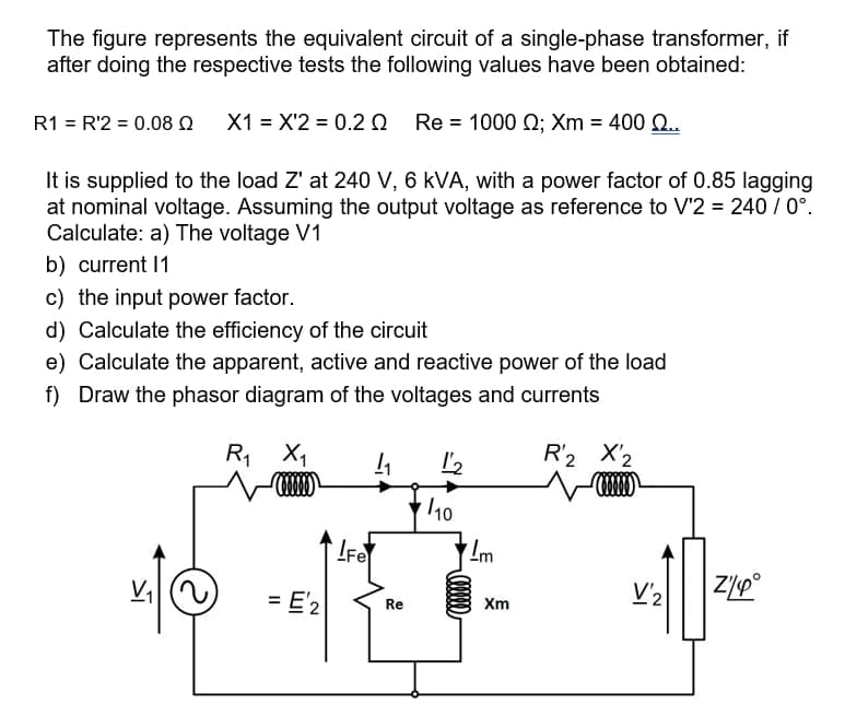
Transcribed Image Text:The figure represents the equivalent circuit of a single-phase transformer, if
after doing the respective tests the following values have been obtained:
R1 = R'2 = 0.08 Q X1 = X'2 = 0.20 Re = 1000 Q; Xm = 400 Q.
It is supplied to the load Z' at 240 V, 6 kVA, with a power factor of 0.85 lagging
at nominal voltage. Assuming the output voltage as reference to V'2 = 240 / 0°.
Calculate: a) The voltage V1
b) current 1
c) the input power factor.
d) Calculate the efficiency of the circuit
e) Calculate the apparent, active and reactive power of the load
f) Draw the phasor diagram of the voltages and currents
R, X1
R'2 X'2
/10
IFe
= E'2
V'2
Re
Xm
Expert Solution
This question has been solved!
Explore an expertly crafted, step-by-step solution for a thorough understanding of key concepts.

Step by step
Solved in 3 steps with 3 images

Knowledge Booster


Learn more about
Need a deep-dive on the concept behind this application? Look no further. Learn more about this topic, electrical-engineering and related others by exploring similar questions and additional content below.Recommended textbooks for you
Power System Analysis and Design (MindTap Course …
Electrical Engineering
ISBN:
9781305632134
Author:
J. Duncan Glover, Thomas Overbye, Mulukutla S. Sarma
Publisher:
Cengage Learning

Electricity for Refrigeration, Heating, and Air C…
Mechanical Engineering
ISBN:
9781337399128
Author:
Russell E. Smith
Publisher:
Cengage Learning
Power System Analysis and Design (MindTap Course …
Electrical Engineering
ISBN:
9781305632134
Author:
J. Duncan Glover, Thomas Overbye, Mulukutla S. Sarma
Publisher:
Cengage Learning
Electricity for Refrigeration, Heating, and Air C…
Mechanical Engineering
ISBN:
9781337399128
Author:
Russell E. Smith
Publisher:
Cengage Learning