The following illustration shows an idealized crane setup for lifting large machinery. The crane's rigid boom ABCD is supported at B by a cable, a rod pinned as D, and at C by a composite column. If the normal stress in the cable and rod should not exceed 70 MPa and the normal strain in the composite column should not exceed 0.1%, determine the maximum mass (in kg) of machinery that the crane can carry. Use r = 3 m. 2r B Aluminum cable: L = 2m E = 70 GPa D = 10 mm Outer: r C Aluminum rod L = 4 m E = 70 GPa D = 25 mm 2r Inner core: D
The following illustration shows an idealized crane setup for lifting large machinery. The crane's rigid boom ABCD is supported at B by a cable, a rod pinned as D, and at C by a composite column. If the normal stress in the cable and rod should not exceed 70 MPa and the normal strain in the composite column should not exceed 0.1%, determine the maximum mass (in kg) of machinery that the crane can carry. Use r = 3 m. 2r B Aluminum cable: L = 2m E = 70 GPa D = 10 mm Outer: r C Aluminum rod L = 4 m E = 70 GPa D = 25 mm 2r Inner core: D

Mechanics of Materials (MindTap Course List)
9th Edition
ISBN:9781337093347
Author:Barry J. Goodno, James M. Gere
Publisher:Barry J. Goodno, James M. Gere
Chapter1: Tension, Compression, And Shear
Section: Chapter Questions
Problem 1.4.17P: Two separate cables AC and BC support a sign structure of weight W = 1575 lb attached to a building....

Related questions

Question
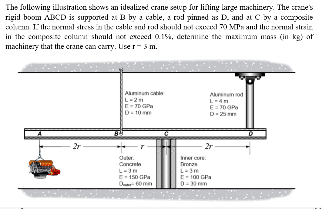
Transcribed Image Text:The following illustration shows an idealized crane setup for lifting large machinery. The crane's
rigid boom ABCD is supported at B by a cable, a rod pinned as D, and at C by a composite
column. If the normal stress in the cable and rod should not exceed 70 MPa and the normal strain
in the composite column should not exceed 0.1%, determine the maximum mass (in kg) of
machinery that the crane can carry. Use r = 3 m.
2r
B
Aluminum cable:
L = 2m
E = 70 GPa
D = 10 mm
r
Outer:
Concrete
L = 3m
E = 150 GPa
Douter= 60 mm
Aluminum rod
L = 4 m
E = 70 GPa
D = 25 mm
2r
Inner core:
Bronze
L = 3m
E = 100 GPa
D = 30 mm
D
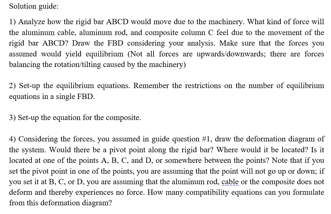
Transcribed Image Text:Solution guide:
1) Analyze how the rigid bar ABCD would move due to the machinery. What kind of force will
the aluminum cable, aluminum rod, and composite column C feel due to the movement of the
rigid bar ABCD? Draw the FBD considering your analysis. Make sure that the forces you
assumed would yield equilibrium (Not all forces are upwards/downwards; there are forces
balancing the rotation/tilting caused by the machinery)
2) Set-up the equilibrium equations. Remember the restrictions on the number of equilibrium
equations in a single FBD.
3) Set-up the equation for the composite.
4) Considering the forces, you assumed in guide question #1, draw the deformation diagram of
the system. Would there be a pivot point along the rigid bar? Where would it be located? Is it
located at one of the points A, B, C, and D, or somewhere between the points? Note that if you
set the pivot point in one of the points, you are assuming that the point will not go up or down; if
you set it at B, C, or D, you are assuming that the aluminum rod, cable or the composite does not
deform and thereby experiences no force. How many compatibility equations can you formulate
from this deformation diagram?
Expert Solution
This question has been solved!
Explore an expertly crafted, step-by-step solution for a thorough understanding of key concepts.

Step by step
Solved in 6 steps with 2 images

Knowledge Booster


Learn more about
Need a deep-dive on the concept behind this application? Look no further. Learn more about this topic, mechanical-engineering and related others by exploring similar questions and additional content below.Recommended textbooks for you
Mechanics of Materials (MindTap Course List)
Mechanical Engineering
ISBN:
9781337093347
Author:
Barry J. Goodno, James M. Gere
Publisher:
Cengage Learning
Mechanics of Materials (MindTap Course List)
Mechanical Engineering
ISBN:
9781337093347
Author:
Barry J. Goodno, James M. Gere
Publisher:
Cengage Learning