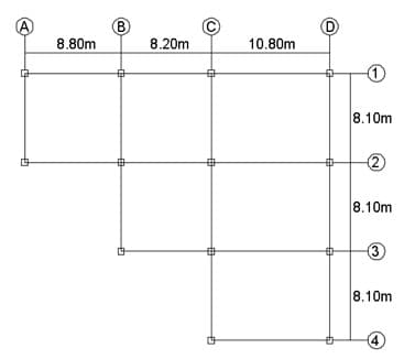
The framing plan of a two-storey post tensioned structure is shown below. Due to some issues, the owner suggest to change the corner columns to equivalent circular columns of the same section modulus as the initial square columns designated as shown in the figure. The size of the square columns is 0.50 by 0.50m. Height per level is 3.60 meters. E = 24.84 x 10⁶ kPa and G = 9.92 x 10⁶ kPa. Use column A-1 as building reference point. Assume the lateral force is acting from north to south direction. Considering the framing plan below as a typical floor framing plan: Set your calculator to 5 decimal places. Determine the stiffness for column D-1. A. 35.6 B. 32.5 C. 31.5 D. 37.4 Determine the stiffness for column 2-D. A. 35.6 B. 32.5 C. 31.5 D. 37.4 Determine the stiffness for column D-3. A. 35.6 B. 32.5 C. 31.5 D. 37.4 Determine the stiffness for column D-4. A. 35.6 B. 32.5 C. 31.5 D. 37.4


The framing plan of a two-storey post tensioned structure is shown below. Due to some issues, the owner suggest to change the corner columns to equivalent circular columns of the same section modulus as the initial square columns designated as shown in the figure. The size of the square columns is 0.50 by 0.50m. Height per level is 3.60 meters. E = 24.84 x 10⁶ kPa and G = 9.92 x 10⁶ kPa. Use column A-1 as building reference point. Assume the lateral force is acting from north to south direction. Considering the framing plan below as a typical floor framing plan: Set your calculator to 5 decimal places.
Determine the stiffness for column D-1.
A. 35.6
B. 32.5
C. 31.5
D. 37.4
Determine the stiffness for column 2-D.
A. 35.6
B. 32.5
C. 31.5
D. 37.4
Determine the stiffness for column D-3.
A. 35.6
B. 32.5
C. 31.5
D. 37.4
Determine the stiffness for column D-4.
A. 35.6
B. 32.5
C. 31.5
D. 37.4

Step by step
Solved in 2 steps with 2 images


