The inr - The inr - The inru w residu.

Power System Analysis and Design (MindTap Course List)
6th Edition
ISBN:9781305632134
Author:J. Duncan Glover, Thomas Overbye, Mulukutla S. Sarma
Publisher:J. Duncan Glover, Thomas Overbye, Mulukutla S. Sarma
Chapter3: Power Transformers
Section: Chapter Questions
Problem 3.14P: A single-phase 50-kVA,2400/240-volt,60-Hz distribution transformer is used as a step-down...

Related questions
Question
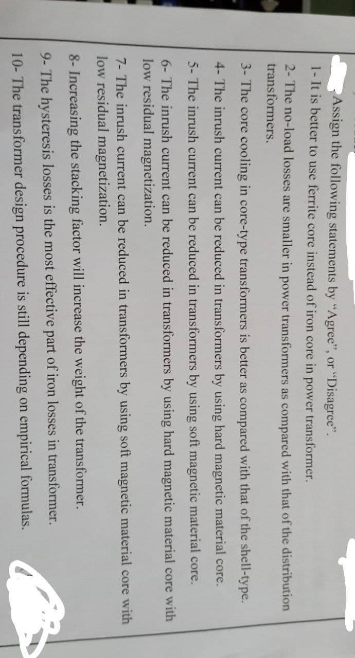
Transcribed Image Text:Assign the following statements by "Agree", or “Disagree".
1- It is better to use ferrite core instead of iron core in power transformer.
2- The no-load losses are smaller in power transformers as compared with that of the distribution
transformers.
3- The core cooling in core-type transformers is better as compared with that of the shell-type.
4- The inrush current can be reduced in transformers by using hard magnetic material core.
5- The inrush current can be reduced in transformers by using soft magnetic material core.
6- The inrush current can be reduced in transformers by using hard magnetic material core with
low residual magnetization.
7- The inrush current can be reduced in transformers by using soft magnetic material core with
low residual magnetization.
8- Increasing the stacking factor will increase the weight of the transformer.
9- The hysteresis losses is the most effective part of iron losses in transformer.
10- The transformer design procedure is still depending on empirical formulas.
Expert Solution
This question has been solved!
Explore an expertly crafted, step-by-step solution for a thorough understanding of key concepts.

Step by step
Solved in 3 steps

Knowledge Booster


Learn more about
Need a deep-dive on the concept behind this application? Look no further. Learn more about this topic, electrical-engineering and related others by exploring similar questions and additional content below.Recommended textbooks for you
Power System Analysis and Design (MindTap Course …
Electrical Engineering
ISBN:
9781305632134
Author:
J. Duncan Glover, Thomas Overbye, Mulukutla S. Sarma
Publisher:
Cengage Learning
Power System Analysis and Design (MindTap Course …
Electrical Engineering
ISBN:
9781305632134
Author:
J. Duncan Glover, Thomas Overbye, Mulukutla S. Sarma
Publisher:
Cengage Learning