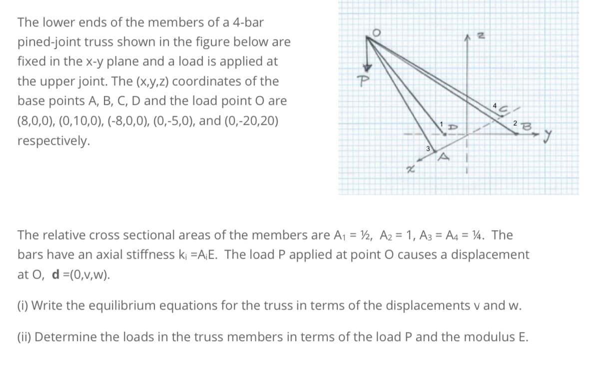
The lower ends of the members of a 4-bar pined-joint truss shown in the figure below are fixed in the x-y plane and a load is applied at the upper joint. The (x,y,z) coordinates of the base points A, B, C, D and the load point O are (8,0,0), (0,10,0), (-8,0,0), (0,-5,0), and (0,-20,20) respectively.
The lower ends of the members of a 4-bar pined-joint truss shown in the figure below are fixed in the x-y plane and a load is applied at the upper joint. The (x,y,z) coordinates of the base points A, B, C, D and the load point O are (8,0,0), (0,10,0), (-8,0,0), (0,-5,0), and (0,-20,20) respectively.

Mechanics of Materials (MindTap Course List)
9th Edition
ISBN:9781337093347
Author:Barry J. Goodno, James M. Gere
Publisher:Barry J. Goodno, James M. Gere
Chapter1: Tension, Compression, And Shear
Section: Chapter Questions
Problem 1.3.13P: A space truss has three-dimensional pin supports at joints 0, B, and C, Load P is applied at joint A...

Related questions

Question
I m posting this question a second time. please solve the correct way
Transcribed Image Text:The lower ends of the members of a 4-bar
pined-joint truss shown in the figure below are
fixed in the x-y plane and a load is applied at
the upper joint. The (x,y,z) coordinates of the
base points A, B, C, D and the load point o are
(8,0,0), (0,10,0), (-8,0,0), (0,-5,0), and (0,-20,20)
respectively.
O
x
3
D
A
2
یاه
13-1
2 B
J
The relative cross sectional areas of the members are A₁ = 1/2, A2 = 1, A3=A4 = 14. The
bars have an axial stiffness ki =A¡E. The load P applied at point O causes a displacement
at O, d =(0,v,w).
(i) Write the equilibrium equations for the truss in terms of the displacements v and w.
(ii) Determine the loads in the truss members in terms of the load P and the modulus E.
Expert Solution
This question has been solved!
Explore an expertly crafted, step-by-step solution for a thorough understanding of key concepts.

This is a popular solution!

Trending now
This is a popular solution!

Step by step
Solved in 5 steps with 5 images

Knowledge Booster


Learn more about
Need a deep-dive on the concept behind this application? Look no further. Learn more about this topic, mechanical-engineering and related others by exploring similar questions and additional content below.Recommended textbooks for you
Mechanics of Materials (MindTap Course List)
Mechanical Engineering
ISBN:
9781337093347
Author:
Barry J. Goodno, James M. Gere
Publisher:
Cengage Learning
Mechanics of Materials (MindTap Course List)
Mechanical Engineering
ISBN:
9781337093347
Author:
Barry J. Goodno, James M. Gere
Publisher:
Cengage Learning