The network shown in the figure below is assembled with uncharged capacitors X, Y, and Z, with Cx 7 uF, Cy=8 μF, and Cz = 5 μF and open switches, S₁ and S2. A potential difference Vab +120 V is applied between points a and b. After the network is assembled, switch S₁ is closed for a long time, but switch S2 is kept open. Then switch S₁ is opened and switch S₂ is closed. What is the final voltage across capacitor X? V₁ = +120 V b (A) 100 V (B) 92 V (C) 76 V (D) 67 V (E) 84 V X Z
The network shown in the figure below is assembled with uncharged capacitors X, Y, and Z, with Cx 7 uF, Cy=8 μF, and Cz = 5 μF and open switches, S₁ and S2. A potential difference Vab +120 V is applied between points a and b. After the network is assembled, switch S₁ is closed for a long time, but switch S2 is kept open. Then switch S₁ is opened and switch S₂ is closed. What is the final voltage across capacitor X? V₁ = +120 V b (A) 100 V (B) 92 V (C) 76 V (D) 67 V (E) 84 V X Z

Delmar's Standard Textbook Of Electricity
7th Edition
ISBN:9781337900348
Author:Stephen L. Herman
Publisher:Stephen L. Herman
Chapter19: Capacitors
Section: Chapter Questions
Problem 1PP: Fill in all the missing values. Refer to the formulas that follow. Resistance Capacitance Time...

Related questions
Question
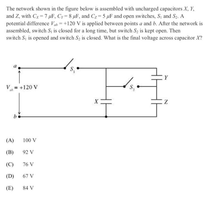
Transcribed Image Text:The network shown in the figure below is assembled with uncharged capacitors X, Y,
and Z, with Cx 7 uF, Cy=8 μF, and Cz = 5 μF and open switches, S₁ and S2. A
potential difference Vab +120 V is applied between points a and b. After the network is
assembled, switch S₁ is closed for a long time, but switch S2 is kept open. Then
switch S₁ is opened and switch S2 is closed. What is the final voltage across capacitor X?
V₁ = +120 V
b
(A)
100 V
(B)
92 V
(C)
76 V
(D)
67 V
(E)
84 V
X
Z
Expert Solution
This question has been solved!
Explore an expertly crafted, step-by-step solution for a thorough understanding of key concepts.

This is a popular solution!

Trending now
This is a popular solution!

Step by step
Solved in 3 steps with 2 images

Recommended textbooks for you
Delmar's Standard Textbook Of Electricity
Electrical Engineering
ISBN:
9781337900348
Author:
Stephen L. Herman
Publisher:
Cengage Learning
Delmar's Standard Textbook Of Electricity
Electrical Engineering
ISBN:
9781337900348
Author:
Stephen L. Herman
Publisher:
Cengage Learning