The rigid bar A,B,C shown in figure is connected to to a steel bar at A, Aluminum bar at B. the properties of the bars are shown on the figure. all the connections are using 12 mm bolts in double shear. Determine the maximum safe load W that can be applied. Determine the final position of point C.
The rigid bar A,B,C shown in figure is connected to to a steel bar at A, Aluminum bar at B. the properties of the bars are shown on the figure. all the connections are using 12 mm bolts in double shear. Determine the maximum safe load W that can be applied. Determine the final position of point C.

Related questions
Question
Transcribed Image Text:0.6 m
0.4 m
Rigid bar
B
C
L = 0.3m
W
L=0.4m
A= 30 x5 mm
A= 50 x 5 mm
E= 100 GPa
E= 60 GPa
allowable stress in tension
= 80 GPa
allowable stress in camp.
= 60 GPa
allowable stress in
tension = 110 MPa
alowable stress in
compression = 90 MPa
Smm
Smm
12 mm bolt in double shear. allowable stresses are
100 MPa in bearing and 40 MPa in shear
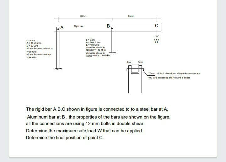
The rigid bar A,B,C shown in figure is connected to to a steel bar at A,
Aluminum bar at B. the properties of the bars are shown on the figure.
all the connections are using 12 mm bolts in double shear.
Determine the maximum safe load W that can be applied.
Determine the final position of point C.
Expert Solution
This question has been solved!
Explore an expertly crafted, step-by-step solution for a thorough understanding of key concepts.

This is a popular solution!

Trending now
This is a popular solution!

Step by step
Solved in 4 steps with 1 images
