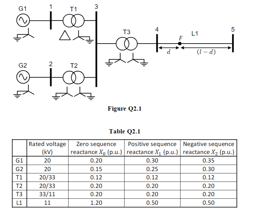
The single line diagram of a power system is shown in Figure Q2.1 including generator and transformer winding connection and earthing details. The parameters for this system have been calculated on a common 100 MVA base and are given in Table Q2.1. All resistances and shunt susceptances are neglected. This system experiences a single line to ground fault at a point F on line L1. The point F is at a distance d from Bus 4 along the line L1. The total length l of the line L1 is 50 km. Note that the location of d is not drawn to scale in Figure Q2.1. The fault current at the fault point F is measured to be 6.106 kA. i) Determine the zero, positive, and negative sequence Thevenin equivalent impedances as seen at the fault point F. These should be evaluated in per unit and shown as a function of d. ii) Use the sequence impedances calculated in part (i) to determine the distance d of the fault (in km) from Bus 4.


Three-Phase Transformers
Three-segment transformers are a type of transformer used to transform voltages of electrical systems into three ranges. Two type transformers are shell-type transformer and core type transformer. In brief, it could be described because of the exquisite kinds of configurations.
Transformer
Ever since electricity has been created, people have started using it in its entirety. We see many types of Transformers in the neighborhoods. Some are smaller in size and some are very large. They are used according to their requirements. Many of us have seen the electrical transformer but they do not know what work they are engaged in.
The single line diagram of a power system is shown in Figure Q2.1 including
generator and transformer winding connection and earthing details. The parameters
for this system have been calculated on a common 100 MVA base and are given in
Table Q2.1. All resistances and shunt susceptances are neglected. This system
experiences a single line to ground fault at a point F on line L1. The point F is at a
distance d from Bus 4 along the line L1. The total length l of the line L1 is 50 km.
Note that the location of d is not drawn to scale in Figure Q2.1. The fault current at
the fault point F is measured to be 6.106 kA.
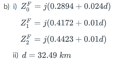
i) Determine the zero, positive, and negative sequence Thevenin equivalent
impedances as seen at the fault point F. These should be evaluated in per unit
and shown as a function of d.
ii) Use the sequence impedances calculated in part (i) to determine the distance d
of the fault (in km) from Bus 4.
It's different from the answer, please don't send it

Step by step
Solved in 5 steps with 9 images


