The solid shaft is fixed in the wall at A (Figure Q2). A force F is applied at B, determine a) the stress components at points D and E, b) the principal stress at each of these points. (Draw free body diagram to show all loading forces and moments) Take F = 12 N and 0 = 45°. A 1,25 mm 6 mm. 8 mm 3 mm F Figure Q2
The solid shaft is fixed in the wall at A (Figure Q2). A force F is applied at B, determine a) the stress components at points D and E, b) the principal stress at each of these points. (Draw free body diagram to show all loading forces and moments) Take F = 12 N and 0 = 45°. A 1,25 mm 6 mm. 8 mm 3 mm F Figure Q2

Mechanics of Materials (MindTap Course List)
9th Edition
ISBN:9781337093347
Author:Barry J. Goodno, James M. Gere
Publisher:Barry J. Goodno, James M. Gere
Chapter7: Analysis Of Stress And Strain
Section: Chapter Questions
Problem 7.3.25P: The stresses at a point on the down tube of a bicycle frame are trx= 4800 psi and t = -1950 psi (see...

Related questions

Question
Urgently need it!
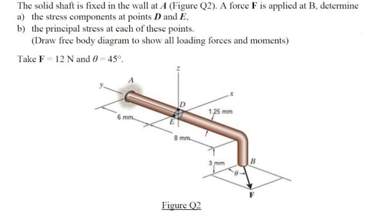
Transcribed Image Text:The solid shaft is fixed in the wall at A (Figure Q2). A force F is applied at B, determine
a) the stress components at points D and E,
b) the principal stress at each of these points.
(Draw free body diagram to show all loading forces and moments)
Take F = 12 N and 0 = 45°.
1,25 mm
6 mm.
8 mm.
3 mm
B
F
Figure Q2
Expert Solution
This question has been solved!
Explore an expertly crafted, step-by-step solution for a thorough understanding of key concepts.

Step by step
Solved in 5 steps with 5 images

Knowledge Booster


Learn more about
Need a deep-dive on the concept behind this application? Look no further. Learn more about this topic, mechanical-engineering and related others by exploring similar questions and additional content below.Recommended textbooks for you
Mechanics of Materials (MindTap Course List)
Mechanical Engineering
ISBN:
9781337093347
Author:
Barry J. Goodno, James M. Gere
Publisher:
Cengage Learning
Mechanics of Materials (MindTap Course List)
Mechanical Engineering
ISBN:
9781337093347
Author:
Barry J. Goodno, James M. Gere
Publisher:
Cengage Learning