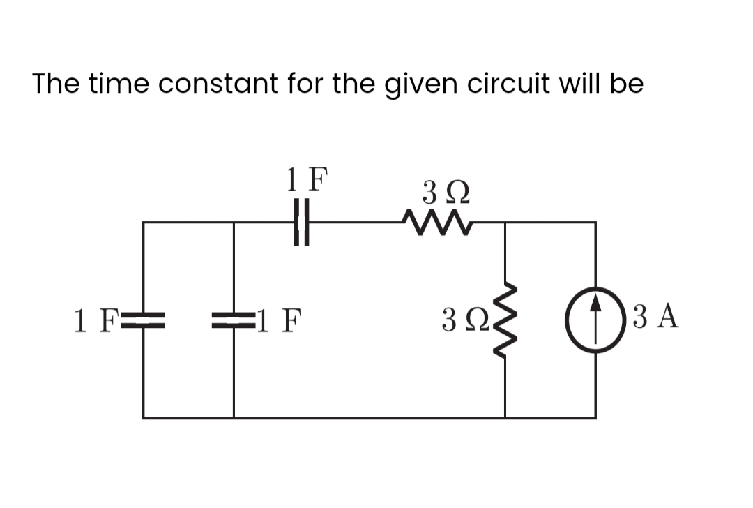
The time constant for the given circuit will be 1 F 1 F 1 F 3 Ω M 3Ω 3 A


Q: Lecture 5 P5.1. For the full-wave rectifier with active load Vrms=120 V, frequency f-60 Hz, load…
A: “Since you have posted a question with multiple sub parts, we will provide the solution only to the…
Q: 3 The signals below represent the equation for waveforms over one period. Plot the following…
A:
Q: Draw the Bode plot for the following
A: The given transfer function is,Ys=501+0.025ss1+0.05s.
Q: x(+) in the input of an LTI system h(t) in the impulse respons of an LTI System y(t) = ?
A:
Q: power delivered
A:
Q: Find the maximum real power that can be transferred to an impedance ZL connected between terminals a…
A:
Q: The transformer at right steps up voltage by a factor of 1.5 (1:1.5), with total turns N-200 a)…
A:
Q: The power across a 3-phase, 3-wire balanced load system is measured by two wattmeter method. One of…
A: Given- 3-phase, 3-wire balanced load system measured by two wattmeter method- One wattmeter…
Q: A 10 MVA, 11 kV, 3-phase star-connected alternator is protected by the Merz-Price balance-current…
A:
Q: Combinational logic circuits' results are entirely determined by their inputs.
A:
Q: A three phase Y‐connected balanced load having phase impedance of 40 + j30, The neutral is…
A: Given Star connected load with phase impedance Z Y =40+ j 30 Ω Neutral to ground impedance =Z n=…
Q: Obtain the truth table of the following functions, and express each function in sum‐of‐minterms and…
A:
Q: 1. Determine whether each of the following signals is periodic. If a signal is periodic, determine…
A: 1) for this question we need to find the system is period or non periodic (aperdioc) a)…
Q: In the experiment set-up, what is the given AC supply R-1500 M Inductance in the 230V L=?
A: Given data, Circuit diagram is given as,
Q: 5. When the modulation percentage is 75, an AM transmitter produces 10 kW. How much of this was…
A: We have given the following problem When the modulation percentage is 75% an AM transmitter radiates…
Q: Find the stability factory with respect to Vbe from 25C to 100C for a fixed bias circuit with Rb =…
A: GIven: Rb = 240k and Beta-100. Vbe@25-0.65, Vbe @ 100 = 0.48. Need to calculate stability factor.
Q: Use mesh/loop analysis Given a = 2, b = 5, c = 2, d = 3, e = 4, f = 2 and x = 60, what is the phasor…
A: The given circuit diagram is shown below, Where,a=2,b=5,c=2,d=3,e=4,f=2,x=60.
Q: Draw a multi-level, multiple-output, circuit equivalent to the following figure using NAND gates…
A: Answer : to draw the given logic diagram in NAND gates form
Q: Example 1. Consider a unity negative feedback system with the following open-loop transfer function.…
A: In this question, A control system is given with Unity feedback system. We need to draw the root…
Q: What is the difference between a TON and RTO timer? Onone O TON is on delay and RTO is off delay…
A: To do: We have to select from the given options for the difference between a TON and RTO timer.
Q: A function y(t) satisfies the following differential equation : dy(t) + y(t) = 8(t) dt where 8(t) is…
A: Given: A function yt satisfies the following differential equation. dytdt+yt=δt. where, δt is delta…
Q: Draw the Bode plot for the following:
A: In this question We need to draw the bode plot for the following. We are solving this problem using…
Q: The action of the two switches in the circuit seen in the figure is as follows. For t < 0, switch 1…
A:
Q: Transfer function
A:
Q: [Q2] Sixteen signals, the bandwidth of each one is 8kHz, are to be transmitted simultaneously by…
A:
Q: 15-Convert decimal number to hexadecimal? 2890 16-Add these hexadecimal numbers: FF + BB 17-Subtract…
A: The required conversion from one base number to another base number can be obtained by converting…
Q: In the experiment set-up, what is the Inductance in the given AC supply R-1500 O a. 0.9 Henry O b.…
A:
Q: 6. Which of the following is not a type of signal is... a. analog signal b. Chain signal c. Binary…
A: Signals It is the function of one or more than one type of independent variable, which provides…
Q: Q1: What is the value of the unknown resistor R in figure shown, if the voltage drop across the 500…
A:
Q: Problems 5.5. A N-turn resonant circular loop with a uniform current distribution and with a…
A:
Q: Consider an LTI system with frequency response 1- e-j²w H(ejw) = 1+ e-j4w Ze -π<ω <π Determine the…
A:
Q: D
A:
Q: 7.53 Determine the inductor current i(t) for both t 0 for each of the circuits in Fig. 7.119.
A: The required parameters can be obtained by analysing the circuit at t less than zero and t after 0.
Q: vi(t)u(t) + R L R C vo(t) See the dynamic RLC circuit shown above. It has a time dependent input of…
A:
Q: 1. Given the following circuit, solve for Io. Must use Superposition Theorem. 12v (Ε 24V (+1) ΑΚΩ…
A:
Q: The switch in the circuit in (Figure 1) has been closed for a long time and opens at t = 0. V = 140…
A:
Q: the circuit Shown below draw the DC-load line and determine the value of R2 so that the Q-Point…
A:
Q: 1. A sinusoidal signal makes 80000 cycles in one minute, what is the period of this signal?
A: 1. Given :- 80000 cycles in 1 minutes Find:- Period of the signal
Q: F = A + (BC) + (BC + AB)(AC)
A:
Q: A 6-pole, 3-phase alternator has 72 slots and its wound double-layer with 5/6 pitch and each coil…
A:
Q: Determine the output waveform for the circuit of Figure +12 V Vin OV -12 V A R www 1.0 ΚΩ ✈ HI V₂
A:
Q: 3.44. The equivalent capacitance of the cir- cuit shown in Fig. 3.1, will be (a) 6F (6) 8 uF (c) 10…
A: Given circuit,
Q: 1. to get the parameters of transformer, what are two most important tests? Cal you draw a test mode…
A: Since you have posted multiple questions, we will provide the solution only to the first question as…
Q: 72 V + 5Ω V 12 Ω 22 (Ohms) 8 Ω Σ 20 Ω a AP4.16_9ed Find the Thévenin equivalent circuit with respect…
A: Simplified circuit for VTH and RTH: Here, we have to find the value of Thevenin voltage and…
Q: 4. Determine and sketch the even and odd parts of the signal depicted in Figure 3. (a) and (b) Label…
A: We need to find out even and odd part for given signal.
Q: Draw schematics for the following circuits. Please provide an extra sheet of paper for your…
A: Here mentioned that five capacitors are connected to cell with voltage V volts and in that 5…
Q: 200 mm square single core copper conductor cable operating at 22kV, 50Hz has the following…
A:
Q: 10. Determine the power density on an earth station from a 5-W satellite source. That is 22,000 mi…
A: Given data, Power is given P=5 W. Distance is given, r=22000 mile,=22000×1609.4,=35405568 m.
Q: EXAMPLE 4.6 A series circuit has R=402 and L=0.01 H. Find the impedance at 100 Hz and 500 Hz.
A: It is given that: R=4 ΩL=0.01 H
Q: Consider the circuit shown in the Fig. below. Suppose that vs(t)=12√2cos(3t) V and C=1/6 F. Find the…
A: In this question We need to determine the complex power across the each element. We know Complex…

Step by step
Solved in 2 steps with 3 images


- Fill in all the missing values. Refer to the formulas that follow. Resistance Capacitance Time constant Total time 150 k 100 F 350 k 35 s 350 pF 10 s 0.05 F 1.2 M 0.47 F 12F 0.05 s 86 k 1.5 s 120 k 470 pF 250 nF 100 ms 8 F 150 s 100 k 150 ms 33 k 4 F =RCR=CC=R Totaltime=5This circuit is connected to a 1000-Hz line. The resistor has a voltage drop of 185 V. the inductor has a voltage drop of 740 V, and the capacitor has a voltage drop of 444 V. The circuit has an apparent power of 51.8 VA. ETITZVA51.8PFER185VIRRPEL740VILXLVARsLLEC444VICXCVARsCCCapacitive Circuits Fill in all the missing values. Refer to the formulas that follow. XC=12fCC=12fXCf=12CXc Capacitance XC Frequency 38 F 60 Hz 78.8 400 Hz 250 pF 4.5 k 234 F 10 kHZ 240 50 Hz 10 F 36.8 560 nF 2 MHz 15 k 60 Hz 75 nF 560 470 pF 200 kHz 6.8 k 400 Hz 34 F 450
- When the following time diagram is completed, how many of the 15 regions are 1? (Qstart = 1)21. The time constant of an RL circuit is the time when the current reaches to what percent of its steady state value? A. 90% C. 57.7% B. 63.2% D. 50%inductance (L) = 8mhDetermine the time constant of the circuit. Calculating the time the circuit is predicted to go into final state.
- The value of x[n] = u[n] + 7 at n = 4 is: (a) 6 (b) 7 (c) 8 (d) 11The circuit shown is at steady state before the switch closes. The inductor's value is L = 3.5 H. Determine iL(t) for t ≥ 0. Answer: (0.514 + 0.286e−4t) AThe current through a 100-uF capacitor is i(t) = 50 sin 120 πt mA. Calculate the voltage across it at t =1 ms and t = 5ms. Take v(0) = 0.
- In the circuit below, the switch closes at time t=0. Assume that Is = 3.14 A, R = 12.1 kΩ, and L = 92 uH. You are told that the current through the inductor just before the switch closes is 2.92 A. Calculate the current through the inductor at time t=1.14 ns.R1 = 750 ohms R2 = 1400 ohms Is = 2mA when t<0 and 0mA when t>=0 It is known that the instantaneous power has a maximum value of 85.88 mW and the first maximum (after t = 0) occurs at 2.581 ms. Find a capacitor and inductor which matches these operating conditions (to the neareast millihenry and microfarad)R = 91 ohm L = 93 H C = 3 mF Can you please find the equation for the voltage across the capacitor ..