The transformation of this filter characteristic can be easily implemented using a single low pass and high pass filter circuits isolated from each other by non-inverting voltage follower, (Av = 1). The output from these two filter circuits is then summed using a third operational amplifier connected as a voltage summer (adder) as shown in Figure 1. R= 10kO 10kO V A Ves o Vour low-pass Summing Amplifier VINO 10 kn V A Ce Re high-pass Figure 1: Band Stop Filter 1. Fill the below table with the components use building the circuit (Figure 1), and their values from the hand calculation part: cales cast. 2020 Component Name Value or Gain Resistors Amplifiers Copyrsho Amercs Collegaof tae
The transformation of this filter characteristic can be easily implemented using a single low pass and high pass filter circuits isolated from each other by non-inverting voltage follower, (Av = 1). The output from these two filter circuits is then summed using a third operational amplifier connected as a voltage summer (adder) as shown in Figure 1. R= 10kO 10kO V A Ves o Vour low-pass Summing Amplifier VINO 10 kn V A Ce Re high-pass Figure 1: Band Stop Filter 1. Fill the below table with the components use building the circuit (Figure 1), and their values from the hand calculation part: cales cast. 2020 Component Name Value or Gain Resistors Amplifiers Copyrsho Amercs Collegaof tae

Introductory Circuit Analysis (13th Edition)
13th Edition
ISBN:9780133923605
Author:Robert L. Boylestad
Publisher:Robert L. Boylestad
Chapter1: Introduction
Section: Chapter Questions
Problem 1P: Visit your local library (at school or home) and describe the extent to which it provides literature...

Related questions
Question
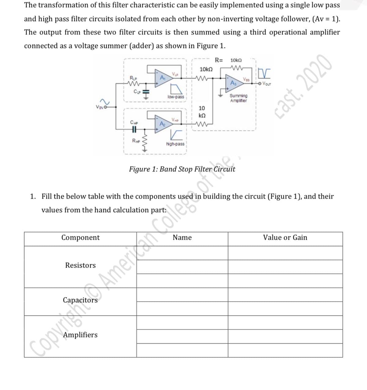
Transcribed Image Text:The transformation of this filter characteristic can be easily implemented using a single low pass
and high pass filter circuits isolated from each other by non-inverting voltage follower, (Av = 1).
%3D
The output from these two filter circuits is then summed using a third operational amplifier
connected as a voltage summer (adder) as shown in Figure 1.
R=
10kO
10kO
V
A
Vas
Lo Vour
Summing
Amplifier
low-pass
VINO
10
ko
V
A
high-pass
Figure 1: Band Stop Filter
1. Fill the below table with the components use
building the circuit (Figure 1), and their
values from the hand calculation part:
Component
Name
Value or Gain
Resistors
Amplifiers
Copyrisht Americs Collegaor tae
Expert Solution
This question has been solved!
Explore an expertly crafted, step-by-step solution for a thorough understanding of key concepts.

This is a popular solution!

Trending now
This is a popular solution!

Step by step
Solved in 4 steps with 1 images

Knowledge Booster


Learn more about
Need a deep-dive on the concept behind this application? Look no further. Learn more about this topic, electrical-engineering and related others by exploring similar questions and additional content below.Recommended textbooks for you
Introductory Circuit Analysis (13th Edition)
Electrical Engineering
ISBN:
9780133923605
Author:
Robert L. Boylestad
Publisher:
PEARSON

Delmar's Standard Textbook Of Electricity
Electrical Engineering
ISBN:
9781337900348
Author:
Stephen L. Herman
Publisher:
Cengage Learning

Programmable Logic Controllers
Electrical Engineering
ISBN:
9780073373843
Author:
Frank D. Petruzella
Publisher:
McGraw-Hill Education
Introductory Circuit Analysis (13th Edition)
Electrical Engineering
ISBN:
9780133923605
Author:
Robert L. Boylestad
Publisher:
PEARSON
Delmar's Standard Textbook Of Electricity
Electrical Engineering
ISBN:
9781337900348
Author:
Stephen L. Herman
Publisher:
Cengage Learning
Programmable Logic Controllers
Electrical Engineering
ISBN:
9780073373843
Author:
Frank D. Petruzella
Publisher:
McGraw-Hill Education

Fundamentals of Electric Circuits
Electrical Engineering
ISBN:
9780078028229
Author:
Charles K Alexander, Matthew Sadiku
Publisher:
McGraw-Hill Education

Electric Circuits. (11th Edition)
Electrical Engineering
ISBN:
9780134746968
Author:
James W. Nilsson, Susan Riedel
Publisher:
PEARSON

Engineering Electromagnetics
Electrical Engineering
ISBN:
9780078028151
Author:
Hayt, William H. (william Hart), Jr, BUCK, John A.
Publisher:
Mcgraw-hill Education,