1 Introduction To Statics 2 Basic Operations With Force Systems 3 Resultants Of Force Systems 4 Coplanar Equilibrium Analysis 5 Three-dimensional Equilibrium 6 Beams And Cables 7 Dry Friction 8 Centroids And Distributed Loads 9 Moments And Products Of Inertia Of Areas 10 Virtual Work And Potential Energy Chapter4: Coplanar Equilibrium Analysis
Chapter Questions Section: Chapter Questions
Problem 4.1P: Each of the bodies shown is homogeneous and has a mass of 30 kg. Assume friction at all contact... Problem 4.2P: Each of the bodies shown is homogeneous and has a mass of 30 kg. Assume friction at all contact... Problem 4.3P: Each of the bodies shown is homogeneous and has a mass of 30 kg. Assume friction at all contact... Problem 4.4P: The homogeneous bar weighs 12 lb. It is resting on friction surfaces at A and B. Draw the FBD of the... Problem 4.5P: The homogeneous beam AB weighs 400 lb. For each support condition shown in (a) through (d), draw the... Problem 4.6P: The homogeneous triangular plate has a mass of 12 kg. Draw the FBD of the plate for each set of... Problem 4.7P: The bracket of negligible weight is supported by a pin at A and a frictionless peg at B, which can... Problem 4.8P: The figure models the handle of the water cock described in Prob. 4.9. Draw the FBD of the handle,... Problem 4.9P: The high-pressure water cock is rigidly attached to the support at D. Neglecting the weights of the... Problem 4.10P: Draw the FBD of the entire frame, assuming that friction and the weights of the members are... Problem 4.11P: The figure is a model for member CDE of the frame described in Prob. 4.10. Draw the FBD of the... Problem 4.12P: The homogeneous cylinder of weight Wrests in a frictionless right-angled corner. In the position... Problem 4.13P: Calculate the force P that is required to hold the 120-lb roller at rest on the rough incline. Problem 4.14P: The 60-lb homogeneous disk is suspended from a belt that runs from B to C. The spring OA holds the... Problem 4.15P: The 180-kg uniform boom ABC, supported by a horizontal cable at B and a pin at A, carries a 320-kg... Problem 4.16P: The table lamp consists of two uniform arms, each weighing 0.6 lb, and a 1.8-lb bulb fixture. If... Problem 4.17P: At what angle will the lamp in Prob. 4.16 be in equilibrium without the couple CA? Problem 4.18P: The bent beam ABC is supported by a pin at B and a roller at C. Neglecting the weight of the beam,... Problem 4.19P: Compute all reactions at the base A of the traffic light standard, given that the tension in the... Problem 4.20P: The man is holding up the 35-kg ladder ABC by pushing perpendicular to the ladder. If the maximum... Problem 4.21P: The 1200-lb homogeneous block is placed on rollers and pushed up the 10 incline at constant speed.... Problem 4.22P: The uniform plank ABC weighs 400 N. It is supported by a pin at A and a cable that runs around the... Problem 4.23P: The center of gravity of the 850-N man is at G. If the man pulls on the rope with a 388-N force,... Problem 4.24P: The homogeneous 340-lb sign is suspended from three wires. Find the tension in each wire. Problem 4.25P: When the truck is empty, it weighs 6000 lb and its center of gravity is at G. Determine the total... Problem 4.26P: The homogeneous bar AB weighs 25 lb. Determine the magnitudes of the forces acting on the bar at A... Problem 4.27P: Determine the smallest horizontal force P that would push the homogeneous cylinder of weight W over... Problem 4.28P: The homogeneous beam AB weighing 800 lb carries the distributed load shown. Find the support... Problem 4.29P: The homogeneous 40-kg bar ABC is held in position by a horizontal rope attached to end C. Neglecting... Problem 4.30P: The horizontal force P is applied to the handle of the puller. Determine the resulting tension T in... Problem 4.31P: The homogeneous plate of weight W is suspended from two cables. Determine the force P that is... Problem 4.32P: Neglecting the mass of the beam, compute the reactions at A and B. Problem 4.33P: The 1200-kg car is being lowered slowly onto the dock using the hoist A and winch C. Determine the... Problem 4.34P: The crate weighing 400 lb is supported by three ropes concurrent at B. Find the forces in ropes AB... Problem 4.35P: Find the smallest value of P for which the crate in the Prob. 4.34 will be in equilibrium in the... Problem 4.36P: Determine the rope tension T for which the pulley will be in equilibrium. Problem 4.37P: The 40-kg homogeneous disk is resting on an inclined friction surface. (a) Compute the magnitude of... Problem 4.38P: The 40-kghomogeneous disk is placed on a frictionless inclined surface and held in equilibrium by... Problem 4.39P: The mass of the uniform bar AB is 80 kg. Calculate the couple C required for equilibrium if (a) =0;... Problem 4.40P: The mechanism shown is a modified Geneva drive-a constant velocity input produces a varying velocity... Problem 4.41P: The center of gravity of the 3000-lb car is at G. The car is parked on an incline with the parking... Problem 4.42P: The 30-lb block is held in place on the smooth inclined plane by the force P. (a) Knowing that =20,... Problem 4.43P: The vertical post is supported by two cables (the cable BFC runs over a smooth peg at F) and an... Problem 4.44P: The uniform ladder of weight W is raised slowly by applying a vertical force P to the rope at A.... Problem 4.45P: The uniform, 30-lb ladder is raised slowly by pulling on the rope attached at A. Determine the... Problem 4.46P: The 90-kg man, whose center of gravity is at G, is climbing a uniform ladder. The length of the... Problem 4.47P: The bar ABC is constrained by the pin support A and the cable BD. Determine the force in the cable... Problem 4.48P: The tensioning mechanism of a magnetic tape drive has a mass of 0.4 kg, and its center of gravity is... Problem 4.49P: The homogeneous 300-kg cylinder is pulled over the 100-mm step by the horizontal force P. Find the... Problem 4.50P: Compute the magnitudes of the reactions at pin A and the roller at D. Neglect the weight of the... Problem 4.51P: Each of the sandbags piled on the 380-lb uniform beam weighs 14 lb. Determine the support reactions... Problem 4.52P: The 18-ft pole is supported by a pin at A and a vertical cable at B. Determine the force in the... Problem 4.53P: The supporting structure of the billboard is attached to the ground by a pin at B, and its rear leg... Problem 4.54P: The self-regulating floodgate ABC, pinned at B, is pressed against the lip of the spillway at C by... Problem 4.55P: The cantilever beam is built into a wall at O. Neglecting the weight of the beam, determine the... Problem 4.56P: Determine the force F required to keep the 200-kg crate in equilibrium in the position shown. Problem 4.57P: The uniform rod AB of weight W is supported by the two inclined planes. Neglecting friction,... Problem 4.58P: A machine operator produces the tension Tin the control rod by applying the force P to the foot... Problem 4.59P: The dump truck consists of a chassis and a tray, with centers of gravity at G1 and G2, respectively.... Problem 4.60P: The centers of gravity of the 50-kg lift truck and the 120-kg box are at G1 and G2, respectively.... Problem 4.61P: (a) draw the free-body diagrams for the entire assembly (or structure) and each of its parts.... Problem 4.62P: (a) draw the free-body diagrams for the entire assembly (or structure) and each of its parts.... Problem 4.63P: For Probs. 4.61–4.68, (a) draw the free-body diagrams for the entire assembly (or structure) and... Problem 4.64P: (a) draw the free-body diagrams for the entire assembly (or structure) and each of its parts.... Problem 4.65P: (a) draw the free-body diagrams for the entire assembly (or structure) and each of its parts.... Problem 4.66P: (a) draw the free-body diagrams for the entire assembly (or structure) and each of its parts.... Problem 4.67P: (a) draw the free-body diagrams for the entire assembly (or structure) and each of its parts.... Problem 4.68P: (a) draw the free-body diagrams for the entire assembly (or structure) and each of its parts.... Problem 4.69P: The two uniform cylinders, each of weight W, are resting against inclined surfaces. Neglecting... Problem 4.70P: Draw the FBDs for the following: (a) bar ABC with pin A inside the bar; (b) bar ABC with pin A... Problem 4.71P: Draw the FBDs for the beam ABC and the segments AB and BC. Note that the two segments are joined by... Problem 4.72P: Draw the FBDs for the entire structure and the member BDE. Count the total number of unknowns and... Problem 4.73P: The beam consists of the bars AB and BC connected by a pin B. Determine the support reactions at A.... Problem 4.74P: For the frame shown, determine the magnitude of the pin reaction at B. Neglect the weight of the... Problem 4.75P: Determine the magnitudes of the pin reactions at A and C. Neglect the weights of the members. Problem 4.76P: The bars AB and AC are joined by a pin at A and a horizontal cable. The vertical cable carrying the... Problem 4.77P: Neglecting the weights of the members, determine the magnitude of the pin reaction at D when the... Problem 4.78P: Calculate the magnitudes of the pin reactions at A and C. Neglect the weights of the members. Problem 4.79P: Determine the magnitude of the pin reaction at A as a function of P. The weights of the members are... Problem 4.80P: Neglecting friction and the weights of the members, compute the magnitudes of the pin reactions at A... Problem 4.81P: When activated by the force P, the gripper on a robotic arm is able to pick up objects by applying... Problem 4.82P: Determine the axle loads (normal forces at A, B, and C) for the ore hauler when it is parked on a... Problem 4.83P: Determine the force P that would produce a tensile force of 25 lb in the cable at E. Neglect the... Problem 4.84P: The pulley-cable system supports the 150-lb weight. The weights of the pulleys and the horizontal... Problem 4.85P: Determine the contact force between the smooth 90-kg ball B and the horizontal bar, and the... Problem 4.86P: Compute the tension in the cable and the contact force at the smooth surface B when the 300-Nm... Problem 4.87P: Determine the magnitude of the pin reaction at B. Neglect the weights of the members. Problem 4.88P: Determine the tension in the cable at B, given that the uniform cylinder weighs 350 lb. Neglect... Problem 4.89P: Compute the magnitude of the pin reaction at B. Neglect the weights of the structural members. Problem 4.90P: Neglecting the weight of the frame, find the tension in cable CD. Problem 4.91P: Determine the clamping force at A due to the 15-lb horizontal force applied to the handle at E. Problem 4.92P: Compute the tension in the cable BD when the 165-lb man stands 5 ft off the ground, as shown. The... Problem 4.93P: Calculate the reactions at the built-in support at C, neglecting the weights of the members. Problem 4.94P: Determine the magnitudes of the roller reactions at C and D. Neglect the weights of the members. Problem 4.95P: The linkage of the braking system consists of the pedal arm DAB, the connecting rod BC, and the... Problem 4.96P: The window washers A and B support themselves and the 40-lb uniform plank CD by pulling down on the... Problem 4.97P: The figure shows a wire cutter. Determine the cutting force on the wire at A when the 75-N forces... Problem 4.98P: Find the tension T in the cable when the 180-N force is applied to the pedal at E. Neglect friction... Problem 4.99P: The 400-kg drum is held by tongs of negligible mass. Determine the magnitude of the contact force... Problem 4.100P: Compute the magnitudes of all forces acting on member CDE of the frame. Problem 4.101P: Calculate all forces acting on member CDB. Problem 4.102P: The automatic drilling robot must sustain a thrust of 32 lb at the tip of the drill bit. Determine... Problem 4.103P: Determine the clamping (vertical) force applied by the tongs at E. Problem 4.104P: Determine the axial force in member BC of the frame. Note the joint D is a sliding pin. Problem 4.105P: Neglecting friction, determine the relationship between P and Q, assuming that the mechanism is in... Problem 4.106P: Find the magnitudes of the pin reactions at A and C. Problem 4.107P: The load in the bucket of a skid steer loader is 600 lb with its center of gravity at G. For the... Problem 4.108P: Determine the magnitude of the roller reaction at E. Problem 4.109P: The tool shown is used to crimp terminals onto electric wires. The wire and terminal are inserted... Problem 4.110P: The 12-lb force is applied to the handle of the toggle cutter. Determine the force exerted by the... Problem 4.111P: The blade of the bulldozer is rigidly attached to a linkage consisting of the arm AB, which is... Problem 4.112P: Find the magnitudes of the pin reactions at A, C, and E caused by the 260-Nm couple. Problem 4.113P: The pins at the end of the retaining-ring spreader fit into holes in a retaining ring. When the... Problem 4.114P: Determine the magnitudes of the support reactions at A, D, and E. Problem 4.115P: Find the magnitude of the pin reaction at C. Assume that the 180-lb force is applied to the pin at... Problem 4.116P: For the pliers shown, determine the relationship between the magnitudes of the applied forces P and... Problem 4.117P: The device shown is an overload prevention mechanism. When the force acting on the smooth peg at D... Problem 4.118P: The figure is a schematic of a wire cutter. Determine the force applied by the cutting blade to the... Problem 4.119P: The hinge shown is the type used on the doors of some automobiles. If a torsion spring at F applies... Problem 4.120P: Determine the force in the hydraulic cylinder EF that would maintain the parallelogram mechanism in... Problem 4.121P: Determine the horizontal force P that would keep the uniform 12-kg rectangular plate in the position... Problem 4.122P: Determine the magnitudes of the forces acting on the bracket at B and C. Problem 4.123P: Determine the angle at which the bar AB is in equilibrium. Neglect friction. Problem 4.124P: The automobile, with center of gravity at G, is parked on an 18 slope with its brakes off. Determine... Problem 4.125P: The figure shows a three-pin arch. Determine the horizontal component of the pin reaction at A... Problem 4.126P: The center of gravity of the nonhomogeneous bar AB is located at G. Find the angle at which the bar... Problem 4.127P: When suspended from two cables, the rocket assumes the equilibrium position shown. Determine the... Problem 4.128P: The pump oiler is operated by pressing on the handle at D, causing the plunger to raise and force... Problem 4.129P: The uniform 240-lb bar AB is held in the position shown by the cable AC. Compute the tension in the... Problem 4.130P: Find the force P required to (a) push; and (b) pull the 80-lb homogeneous roller over the 3-in.... Problem 4.131P: Using the method of joints, calculate the force in each member of the trusses shown. State whether... Problem 4.132P: Using the method of joints, calculate the force in each member of the trusses shown. State whether... Problem 4.133P: Using the method of joints, calculate the force in each member of the trusses shown. State whether... Problem 4.134P: Using the method of joints, calculate the force in each member of the trusses shown. State whether... Problem 4.135P: Using the method of joints, calculate the force in each member of the trusses shown. State whether... Problem 4.136P: Using the method of joints, calculate the force in each member of the trusses shown. State whether... Problem 4.137P: Using the method of joints, calculate the force in each member of the trusses shown. State whether... Problem 4.138P: Using the method of joints, calculate the force in each member of the trusses shown. State whether... Problem 4.139P: Using the method of joints, calculate the force in each member of the trusses shown. State whether... Problem 4.140P: Using the method of joints, calculate the force in each member of the trusses shown. State whether... Problem 4.141P: Identify all the zero-force members in the four trusses shown. Problem 4.142P: The walkway ABC of the footbridge is stiffened by adding the cable ADC and the short post of length... Problem 4.143P: Find the force in member EF. Problem 4.144P: Determine the forces in members AE, BE, and ED. Problem 4.145P: Determine the reaction at E and the force in each member of the right half of the truss. Problem 4.146P: Determine the force in member AD of the truss. Problem 4.147P: Determine the force in member BE of the truss. Problem 4.148P: Show that all diagonal members of the truss carry the same force, and find the magnitude of this... Problem 4.149P: Determine the forces in members FG and AB in terms of P. Problem 4.150P: Determine the forces in members BC, BG, and FG. Problem 4.151P: Determine the forces in members EF, BF, and BC. Problem 4.152P: Compute the forces in members EF, NE and NO. Problem 4.153P: Repeat Prob. 4.152 assuming that the 400-kN force is applied at O instead of L. Problem 4.154P: Determine the forces in members BG, CI, and CD. Problem 4.155P: Assuming that P=48000lb and that it may be applied at any joint on the line FJ, determine the... Problem 4.156P: Calculate the forces in members BC, CF, and FG. Problem 4.157P: Find the forces in members CD, DH, and HI. Problem 4.158P: Determine the forces in members CD and DF. Problem 4.159P: Compute the forces in members CD and JK, given that P=300lb and Q=1000lb. (Hint: Use the section... Problem 4.160P: If PCD=6000lb and PGD=1000lb (both compression), find P and Q. Problem 4.161P: Determine the forces in members EF, BF, and BC. Problem 4.162P: Determine the forces in members AC, AD, and DE. Problem 4.163P: Determine the forces in members GI, PH, and GH. Figure P4.162, P4.163 Problem 4.164P: Determine the forces in members CD, IJ, and NJ of the K-truss in terms of P. Problem 4.165P: Calculate the forces in members AB and DE. Problem 4.166P: (a) Find the forces in members CE, CF, and DF. (b) Identify all the zero -force members. Problem 4.167P: Determine the forces in members BC and BE and the horizontal pin reaction at G. Problem 4.168P: A couple acting on the winch at G slowly raises the load W by means of a rope that runs around the... Problem 4.169RP: The uniform, 20-kg bar is placed between two vertical surfaces. Assuming sufficient friction at A to... Problem 4.170RP: The 320-lb homogeneous spool is placed on the inclined surface. Determine the vertical force P that... Problem 4.171RP: Determine the magnitude of the pin reaction at A, assuming the weight of bar ABC to be negligible. Problem 4.172RP: Determine the couple C that will hold the bar AB in equilibrium in the position shown. Neglect the... Problem 4.173RP: The 800-lb force is applied to the pin at E. Determine the magnitude of the force exerted by pin E... Problem 4.174RP: The weight W=6kN hangs from the cable which passes over the pulley at F. Neglecting the weights of... Problem 4.175RP: The 2000-lb and 6000-lb forces are applied to the pins at B and C, respectively. Calculate the... Problem 4.176RP: The two couples act at the midpoints of bars AB and BD. Determine the magnitudes of the pin... Problem 4.177RP: Determine the forces in members AC and AD of the truss. Problem 4.178RP: Determine the angle for which the uniform bar of length L and weight W will be in equilibrium.... Problem 4.179RP: Determine the magnitude of the force exerted by the pin at E on member ACE. Assume that the forces... Problem 4.180RP: Calculate the forces in members (a) DE; (b) BE; and (c)BC. Indicate tension or compression. Problem 4.181RP: Determine the ratio P/Q for which the parallel linkage will be in equilibrium in the position shown.... Problem 4.182RP: The 30-lb block C rests on the uniform 14-lb bar AB. The cable connecting C to B passes over a... Problem 4.183RP: The 30-lb homogeneous bar AB supports the 60-lb block. The ends of the bar rest on frictionless... Problem 4.184RP: Determine the forces in members (a) EF; and (b) BC. Indicate tension or compression. Problem 4.185RP: Find the magnitude of the pin reaction at B caused by the weight W=80lb. Neglect the weights of the... Problem 4.186RP: The breaking strength of the cable FG that supports the portable camping stool is 400 lb. Determine... Problem 4.187RP: Determine the forces in members GH, BH, and BC of the truss. Problem 4.188RP: The 80-N force is applied to the handle of the embosser at E. Determine the resulting normal force... Problem 4.189RP: The tongs shown are designed for lifting blocks of ice. If the weight of the ice block is W, find... Problem 4.119P: The hinge shown is the type used on the doors of some automobiles. If a torsion spring at F applies...
Related questions
Concept explainers
(ENGINERRING MECHANICS ) ALREADY ANSWERED IN BARTLEBY. PLEASE DRAW THE FREE-BODY DUAGRAM UPVOTE WILL BE GIVEN. PLEASE WRITE THE COMPLETE SOLUTIONS. SOLVE IN 6 DECIMAL PLACES. BOX THE FINAL ANSWERS.)
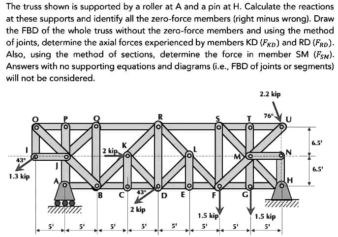
Transcribed Image Text: The truss shown is supported by a roller at A and a pin at H. Calculate the reactions
at these supports and identify all the zero-force members (right minus wrong). Draw
the FBD of the whole truss without the zero-force members and using the method
of joints, determine the axial forces experienced by members KD (FKD) and RD (FRD).
Also, using the method of sections, determine the force in member SM (FSM).
Answers with no supporting equations and diagrams (i.e., FBD of joints or segments)
will not be considered.
43°
1.3 kip
5¹
2 kip
5'
K
C
43°
2 kip
5'
DE
5'
F
1.5 kip
5'
2.2 kip
76⁰
1.5 kip
5'
-------
N
H
6.5'
6.5'
Branch of science that deals with the stationary and moving bodies under the influence of forces.
Expert Solution
This question has been solved!
Explore an expertly crafted, step-by-step solution for a thorough understanding of key concepts.
Step 1: The free body diagram of the given truss
VIEW
Step 2: Using equilibrium conditions to
VIEW Step 3: Using method of joint
VIEW Step 4: Similarly using method of joint
VIEW
Step by step
Solved in 5 steps with 6 images