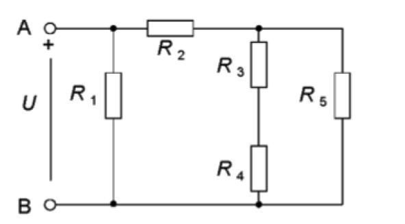
U = 82 V, R1 = 8.2 Ω R2 = 2.7 Ω R3 = 6.3 Ω R4 = 4.6 Ω R5 = 5.6 Ω Calculate: a) the resistance R12345 between points A and B when no voltage source is connected To solve sub-task a) we first count the replacement resistors: - Resistors R3 and R4 are connected in series and their replacement resistance R34 is: Ω. Resistor R5 and replacement resistor R34 are connected in parallel and the resistance of R345 is: Ω. Resistor R2 and replacement resistor R345 are connected in series and replacement resistor R2345 is: Ω. - Now you can calculate sub-task a). b) the current IR5 through R5 so the voltage source is connected. To solve sub-task b) we calculate as follows: - Power from the source: - The current through the travel tower R1: - The current through the replacement resistor R2345: - Now we calculate voltage drops across R2: - Now we calculate voltage drops over compensation resistance R345: : The resistors R2 and R345 are connected in series, ie the sum of voltage drops U2 and U345 is equal to the voltage of the source. Check that it's correct. - Now we count the current through R34: - Now you can count sub-task b) in the same way as you counted the current through R34. c) the voltage UR4 over R4 when the voltage source is connected . To solve sub-task c) we calculate as follows: - The resistors R3 and R4 are connected in series, ie they have the same current that passes through both redistors I34 but divide the voltage into two voltage drops UR3 and UR4. The voltage across R3 is: - Now you can calculate sub-task c) in the same way as you calculated the voltage across R4. Resistors R3 and R4 are connected in series, ie the sum of voltage drops UR3 and UR4 is equal to voltage UR345; Check if it is correct.


KVL and KCL
KVL stands for Kirchhoff voltage law. KVL states that the total voltage drops around the loop in any closed electric circuit is equal to the sum of total voltage drop in the same closed loop.
Sign Convention
Science and technology incorporate some ideas and techniques of their own to understand a system skilfully and easily. These techniques are called conventions. For example: Sign conventions of mirrors are used to understand the phenomenon of reflection and refraction in an easier way.
U = 82 V,
R1 = 8.2 Ω
R2 = 2.7 Ω
R3 = 6.3 Ω
R4 = 4.6 Ω
R5 = 5.6 Ω
Calculate:
a) the resistance R12345 between points A and B when no voltage source is connected
To solve sub-task a) we first count the replacement resistors:
- Resistors R3 and R4 are connected in series and their replacement resistance R34 is:
Ω.
Resistor R5 and replacement resistor R34 are connected in parallel and the resistance of R345 is:
Ω.
Resistor R2 and replacement resistor R345 are connected in series and replacement resistor R2345 is:
Ω.
- Now you can calculate sub-task a).
b) the current IR5 through R5 so the voltage source is connected.
To solve sub-task b) we calculate as follows:
- Power from the source:
- The current through the travel tower R1:
- The current through the replacement resistor R2345:
- Now we calculate voltage drops across R2:
- Now we calculate voltage drops over compensation resistance R345:
: The resistors R2 and R345 are connected in series, ie the sum of voltage drops U2 and U345 is equal to the voltage of the source. Check that it's correct.
- Now we count the current through R34:
- Now you can count sub-task b) in the same way as you counted the current through R34.
c) the voltage UR4 over R4 when the voltage source is connected
.
To solve sub-task c) we calculate as follows:
- The resistors R3 and R4 are connected in series, ie they have the same current that passes through both redistors I34 but divide the voltage into two voltage drops UR3 and UR4. The voltage across R3 is:
- Now you can calculate sub-task c) in the same way as you calculated the voltage across R4.
Resistors R3 and R4 are connected in series, ie the sum of voltage drops UR3 and UR4 is equal to voltage UR345;
Check if it is correct.


Trending now
This is a popular solution!

Step by step
Solved in 3 steps


