Use an ideal op amp to design an inverting integrator with an input resistance of 20k2 and an integration time constant of Ims. What is the value of C, the gain magnitude and phase angle of this circuit at 25 rad/s. O C= 50nF, Gain= 20, phase =90 O C= 0.5nF, Gain= 40, phase =90 O C= 0.05UF, Gain= 40, phase =90 O C= 100F, Gain= 55, phase =90
Use an ideal op amp to design an inverting integrator with an input resistance of 20k2 and an integration time constant of Ims. What is the value of C, the gain magnitude and phase angle of this circuit at 25 rad/s. O C= 50nF, Gain= 20, phase =90 O C= 0.5nF, Gain= 40, phase =90 O C= 0.05UF, Gain= 40, phase =90 O C= 100F, Gain= 55, phase =90

Delmar's Standard Textbook Of Electricity
7th Edition
ISBN:9781337900348
Author:Stephen L. Herman
Publisher:Stephen L. Herman
Chapter18: Resistive-inductive Parallel Circuits
Section: Chapter Questions
Problem 13PP: In an R-L parallel circuit, IT=1.25 amps, R=1.2k, and XL=1k. Find IR

Related questions
Question
100%
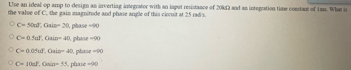
Transcribed Image Text:Use an ideal op amp to design an inverting integrator with an input resistance of 20KQ and an integration time constant of Ims. What is
the value of C, the gain magnitude and phase angle of this circuit at 25 rad/s.
O C= 501F, Gain= 20, phase =90
O C= 0.5nF, Gain= 40, phase =90
O C= 0.05UF, Gain= 40, phase =90
O C= 10NF, Gain= 55, phase =90
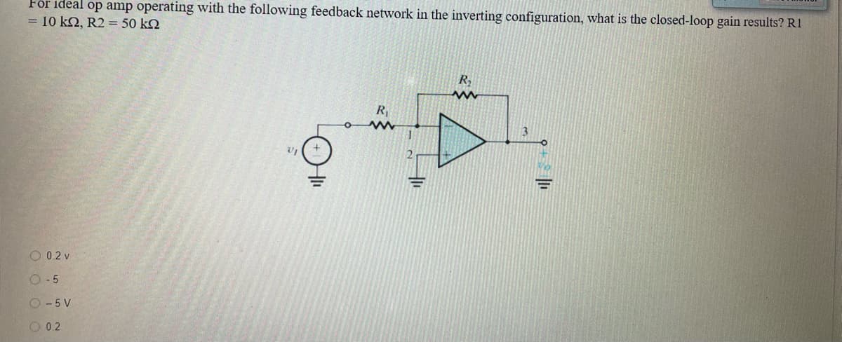
Transcribed Image Text:För ideal op amp operating with the following feedback network in the inverting configuration, what is the closed-loop gain results? R1
= 10 k2, R2 = 50 k2
R
3.
O 0.2 v
O- 5
O - 5 V
O 0.2
Expert Solution
This question has been solved!
Explore an expertly crafted, step-by-step solution for a thorough understanding of key concepts.

This is a popular solution!

Trending now
This is a popular solution!

Step by step
Solved in 2 steps

Knowledge Booster


Learn more about
Need a deep-dive on the concept behind this application? Look no further. Learn more about this topic, electrical-engineering and related others by exploring similar questions and additional content below.Recommended textbooks for you
Delmar's Standard Textbook Of Electricity
Electrical Engineering
ISBN:
9781337900348
Author:
Stephen L. Herman
Publisher:
Cengage Learning
Delmar's Standard Textbook Of Electricity
Electrical Engineering
ISBN:
9781337900348
Author:
Stephen L. Herman
Publisher:
Cengage Learning