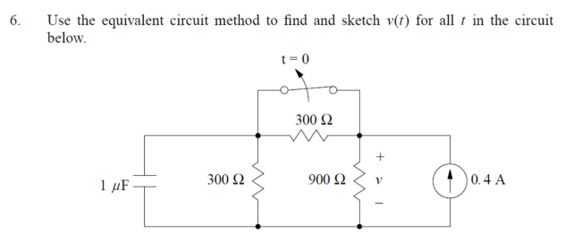
Use the equivalent circuit method to find and sketch v(t) for all in the circuit below. 1 μF. 300 Ω t=0 300 £2 900 £2 0.4 A


Q: 1) For the circuit below, find Ix using mesh analysis: 5 Ω M 1+ 6 V 10 Ω +1 · 1 Ω 8V Ix ww 20 4 Ω
A: Given:
Q: Prob. A.3: Neglecting the base currents in the circuit shown in Fig. So a. Determine Rez such that…
A:
Q: 25. If D = 4x³a, - 2za, - 2ya, C/m², find: (a) ▼ · D; (b) p, at P(x,y,z); (c) the total charge lying…
A: “Since you have posted a question with multiple sub-parts, we will solve first three subparts for…
Q: (a) After being closed for a long time, the switch in the circuit opens at t = 0. Compute i, (t) for…
A: We need to find out the current through the inductor for given circuit .
Q: Find I, 12 V + 12 se 3 MN 13 3 م3 and Vx. Use Cramer's Rule 100 1222 M 28A 20V
A: Given:
Q: The switch has been closed for a long time. For the circuit below: 1) Write the differential…
A: In this question, We need to determine the voltage across the resistance R= 2 ohm We know Inductor…
Q: 9.90 Given the network in Fig. P9.90, determine the input voltage 404 pistoj sluento wwm 0.10 j0.10…
A: For the given network calculation of input voltage Vs. Let us calculate the individual current…
Q: Embedded systems may be networked. O True O False
A:
Q: Explain their definition,comparisons, differences and how they work in a pulse analog modulation:…
A: To Explain: Sampling rate Pulse Amplitude Modulation Pulse Width Modulation
Q: 2.) By Applying kirchoff's Current Law. Find The current I. and the Power of independent source 8A…
A: Given: A network with dependent and independent current source. To find: the value of I
Q: *P5.53. Solve for the node voltages shown in Figure P5.53. 10 Ω V₁ +j20 Ω 10/0° + 1₂ V₂ ..| 15 Ω…
A:
Q: It is known that G(s) = K(s + 2) 54 +5³ +5² + s-4' and the closed-loop structure is shown below:…
A:
Q: Figure 1 shows a diagram for an automobile alarm circuit used to detect certain undesirable…
A: This is a problem of digital circuits. It is given that there are 3 inputs and one output. Let '0'…
Q: Determine if the systems y(n) are linear and shift-invariant: a) y(n) = L[x(n)] = x(n+2) – x(2-n)…
A: We need to check whether the given system is linear or time invariant .
Q: 1. Find the voltage of R4 and R3. 2. Determine the current of R3 in amperes.
A: We are authorized to answer one question at a time, since you have not mentioned which question you…
Q: The transfer function of a system is 2s² + 6s+5 (s + 1)² (s+2) The characteristic equation of the…
A: Transfer function = 2s2+6s+5s+12s+2
Q: If a 12-Q resistor is connected across a-b, determine its power terminals absorbed. 15 V +1 3Ω 4 A 3…
A:
Q: A Wye-Delta transformer is connected t0 66 kV input three-phase transmission line. Each transformer…
A: Given: The star to delta transformer: The rating of the transformer is 1000 kVA The ratio is 8:1
Q: Find the voltage across the capacitor in Fig. L3.1 as a function of time if the capacitor was…
A:
Q: Determine V1 and V2
A: It is given that:
Q: The cross-sectional area of a transform limb is 80 cm² and the volume of the transformer ca is 5000…
A:
Q: Problem 1: The circuit shown in the figure is in a dark room. When the bright light is turned on,…
A: SCR (Silicon controlled rectifier ) or Thyristor is a semi-controlled power switch in which its on…
Q: Can we connect a single-phase motor to operate from a three-phase power source? Explain your answer.
A: In the given questions, we need to explain about the connection of single phase motor with three…
Q: Task 1: Write the truth table for both full and half adders as well as the simplified equations.…
A: In a single bit full adder, the input is 3 bit i.e. input carry, A and B and output is 2 bits i.e.…
Q: An ultrasonic sensor to detect the distance of the material sent out a 40 kHz pulse. The time it…
A: Given, Ultrasonic sensor has Frequency of transmitting sound pulse = frequency of received sound…
Q: The power customer has four circuits of220-volt three phase. The circuits have the maximum demand as…
A:
Q: 9.102 For the BiCMOS differential amplifier in Fig. P9.102 let VDD = Vss=3 V, 1 = 0.2 mA, kW/L = 6.4…
A:
Q: Loov Vi -100v 3.6 wor S₁ Ši Compute for V2.2 k
A: Given: Input voltage waveform, Circuit diagram,
Q: 2.36 Find i and V, in the circuit of Fig. 2.100. 20 1′′ 80 Ω 60 Ω 24 Ω 25 Ω ww 20 Ω 20 Ω 50 Ω www 30…
A: Calculation of i and V0 of the given circuit: To solve this circuit, here we have to apply…
Q: Use the node-voltage method to find the power p4A, in Wa 1:5 +1
A:
Q: For a series RC with R=10 ohms and C=0,2 F. Solve for Xs) when Vo is at the Resistor?
A:
Q: What is the relationship between the voltage in the coil and the current in the coil, what is the…
A:
Q: Given the circuit below with the switch closed for a long time, then opening at t=0, and with the…
A: The question is based on transient analysis of an RC circuit. The concept used is that under steady…
Q: What are the electrical systems used in banks for lighting purposes?
A: Types of lighting Intra-cloud lightning cloud-ground lightning Lightning leads to Very high…
Q: A real-valued periodic signal r(t) has the following Fourier series representation 8 (a) 13 (b) 17…
A: We need to select correct option for power for given signal .
Q: In a p+-n junction diode, if the minority carrier recombination rate is increased by 100 times, how…
A: A p-n junction is a two-terminal device in which the p-terminal is kept at a higher potential than…
Q: (b) Determine the conduction states of the diodes (On or OFF) in the circuits shown in Fig.2. Also,…
A: The given circuit is:
Q: 1. . Given the Boolean function F = xyz + xyz + xyz a. List the truth table of the function. b. Draw…
A:
Q: Let r(t) = 3e-³tu(t - 2). (a) Sketch r(t). = (b) Derive the Laplace transform X(s) L{x(t)} using the…
A:
Q: a single-stage impluse generator has a 0.01 micro farad capacitor. the wave front and wave tail…
A: Given: Single phase generator, Capacitor, C1=0.01 μF C2=1200 pF Resistor, R1=800Ω R2=3000Ω
Q: If a charge of 4.0 mC can transfer in a time of 2.0 ms. What current, in ?(Ampere), does this…
A: Given data, Charge is given Q=4 mC=4×10⁻³ C. Time is given T=2 ms=2×10⁻³ sec.
Q: Given the ff. 1 kHz 5V peak-to-peak sine wave. 0-3.3 V square wave with a period of 12.5μs 200 Hz…
A:
Q: Plot the spectrum for the following signals: a) f(t) = cos(10t) b) f(t) = cos² (10t) c) f(t) = cos³…
A: We need to find out the Fourier transform of given signal and we need to plot them .
Q: Which instrument is capable of determining the distance between the damaged portion of a cable and…
A: A power system's fault analysis is necessary to give data for the selection of switchgear, conductor…
Q: What is the distance between adjacent minimum and maximum current in degrees?
A: We need to find out angle between adjacent maximum and minimum .
Q: Given h(n) and x(n) find the output y(n) = h(n) * x(n). Where h(n) = {1,0,1,0,1} and x(n) =…
A:
Q: Design the logic diagram of the Odd-Parity-Generator with the Truth table.
A: We need to design logic diagram of odd parity generator. And need to draw the truth table.
Q: Cosine Signal Question 2. Consider the cosine 2 Where f=5+(SSS1+SSS2)/1000, where SSS1 and SSS2 are…
A:
Q: Which of these op-amp circuits is commonly found in all types of ADC circuit? O Comparators O…
A: We need to determine the following i) the op-amp circuits present in all types of ADC circuit...?…
Q: 7. Draw the D Flip Flop circuit 8. Produce a truth table for the D Flip Flop circuit
A: D Flip-Flop:- The D flip-flop has a single digital input labeled "D" and is a timed flip-flop. The…

Step by step
Solved in 3 steps with 2 images

- given circuit, Vk = 12 V, R = 240 Ω, C = 1 μF, L = 40 mH. Theswitch, is closed for a long time for t < 0– . Determine vL(t) for t > 0.A series connection of a 30-ohm resistor and a 100-mH inductor is connected across 240-V, 60-Hz supply. What will be the resulting equation of the current? a. i(t) = 7.04 sin(377t + 51.49°) b. i(t) = 7.04 sin(377t - 51.49°) c. i(t) = 4.98 sin(377t - 51.49°) d. i(t) = 4.98 sin(377t + 51.49°)An R-L circuit takes a current 7A that lags behind the 231 V source by 35electrical degrees. Calculate the power factor, impedance, resistance, andinductive reactance of the circuit.
- The current through a 0.5 F capacitor is i(t) = 6(1 - et) A, with-t in seconds. Determine the power in Watts at t = 2 s. Assume voltage at the start time of t = 0 is v(O) = 0.Va = 18V, Vb = 43V, Ic = 14mA. The circuit is in dc steady state. Use superposition. Considering ONLY the contribution of the voltage source, Vb, Determine V1. Enter your answer in V rounded to one decimal place.The voltage and current at the terminals of the circuit element are zero for t<0. For t≥0 they are v=(1500t+1)e−750t V,t≥0;i=40e−750t mA,t≥0. Find the total energy delivered to the circuit element inmicrojoules.
- A series circuit of two pure elements has an applied voltage of 200sin(100t+30)V. Determine the resulting steady-state current of the two elements are:a) R = 300 L =2.5 Hb) R = 400, Xc= 150 c) R = 250, C = 100u d) R = 120, Xl=30070. Ideal inductors and capacitors are 90 degrees out of phase with each other. True False 71. Ideal inductors and resistors are 180 degrees out of phase with each other. True False 72. Impedance of a circuit can be represented or expressed in complex form. True FalseWrite an expression for the output voltage vo(t) ofthe circuit shown if R1 = 1 k , R2 =2 k , R3 =47 k , v2(t)=(0.01 sin 3770t) V, andv1(t)=(0.04 sin 10000t)V. Write an expression forthe voltage appearing at the summing junction (v−).
- 5.A RL circuit has no applied emf, a resistance of Rohms, an inductance of 2 henries, and an initial current of 10 amperes. Find the current in the circuit at any time t. Use R = 50a series rlc circuit having values of pure resistance r=40 ohms and pure inductance l = 50.07 mh. the circuit draws 10 A of current when it is connected across a 400 v , 50hz ,ac supply. calculate the (1) capacitor value and (2) power factor of circuit.In the following circuit shown, the input is the independent source voltage, which is v_s (t) = 9.10 cos (3t + 80 °) V. The output is the voltage of the 5 ohm resistor, denoted by v_o (t). Determine the capacitance (C) and resistance (R), which cause the output voltage to be v_o (t) = 4.43 cos (3t + 93 °) V.