Use the graphical method to construct the shear-force and bending-moment diagrams for the beam shown. Let a=3.5 m, b=5.0 m, Mg = 60 kN-m and Mc 85 kN-m. Construct the shear-force and bending-moment diagrams on paper and use the results to answer the questions in the subsequent parts of this GO exercise. Mg Mc
Q: Use the graphical method to construct the shear-force and bending-moment diagrams for the beam…
A:
Q: 4.Three members of a frame on a knot plate can be seen in the picture below. Determine the size and…
A:
Q: Use the graphical method to construct the shear-force and bending-moment diagrams for the beam…
A:
Q: shear-force and bending-moment diagrams
A: ∑ME=0Ay*20=45*3.5+5.5*9*12Ay=37.575 kip ∑Fy=0Ey+37.575=5.5*9+45Ey=56.925 kip Shear force at x=0 ;…
Q: Required information A rope connecting points A and B supports the force Fshown in the figure. Write…
A: This problem is based on Vectors:
Q: Q5. (50k} N The distance from A to B is d = 400 mm. Determine the following, and В describe each…
A: The location of A and B are given as : A = (0.35,0,0) B=(0.35,-4cos30°,4sin30°)=(0.35,-3.464,2)…
Q: Determine the bending moment acting at each of the following locations: (a) x = 3.5- m (i.e., just…
A:
Q: Consider the following truss system. All bars are either vertical, horizontal, or at 60° from…
A: To find: The force balance matrix. Given: All the bar are either vertical, horizontal or 60° from…
Q: 21. A rigid link PQ is 2 m long and oriented at 20° to the horizontal as shown in the figure. The…
A:
Q: C4.4 The cantilever beam AB of length L carries a distributed loading w that varies with the…
A:
Q: Use the graphical method to construct the shear-force and bending-moment diagrams for the beam…
A: To find : The bending moment and shear moment diagram by using graphical method. Free body diagram…
Q: Use the graphical method to construct the shear-force and bending-moment diagrams for the beam…
A:
Q: Note that x = 0 at support A. When entering your answers, use the bending-moment sign convention…
A:
Q: Q20 Which is the greater moment if we use 50N in both but the arm = .2m in first trail %3D and 0.5…
A:
Q: In Fig. 8.32 two tunnels AB and EF are being driven forward until they meet in order to accommodate…
A:
Q: Use the graphical method to construct the shear-force and bending-moment diagrams for the beam…
A:
Q: Use the graphical method to construct the shear-force and bending-moment diagrams for the beam…
A:
Q: 240.0 50.194 7. 5. 3. 71.565 1. One grid line = 1 foot. 1. Draw the arrows and label the reaction…
A: The above question to the trusses, which are generally solved by the three static equations which…
Q: Use the graphical method to construct the shear-force and bending-moment diagrams for the beam…
A:
Q: Determine the magnitude and coordinate direction angles of the resultant force. 0.75 m FAR = 250 N…
A: Given, FAC = 400 N FAB = 250 N
Q: Use the graphical method to construct the shear-force and bending-moment diagrams for the beam…
A: A beam is defined as a structural member subjected to transverse shear load during its…
Q: Use the graphical method to construct the shear-force and bending-moment diagrams for the beam…
A:
Q: 1 500 Ib/ft В 6 000 lb - 4 ft – 6 ft <
A:
Q: Determine the shear force acting at each of the following locations: (a) x = 0+ m (i.e., just to the…
A:
Q: 3. Determine the most unfavorable arrangement of the crane loads and compute the maximum and minimum…
A: given data; ⇒reaction force at point A=RA⇒reaction force at point B=RB
Q: Use the graphical method to construct the shear-force and bending-moment diagrams for the beam…
A:
Q: For the beam shown, the magnitude of the distributed load is wo = 11.8 kN/m and the beam length is L…
A:
Q: b)A simply supported beam has a symmetrical rectangular cross-section. If the second moment of area…
A: Given data:-Area MOI of cross-section about x-axis, Ix=11.5×106mm4depth of cross-section, d=180mmThe…
Q: Use the graphical method to construct the shear-force and bending-moment diagrams for the beam…
A:
Q: C4.4 The cantilever beam AB of length L carries a distributed loading w that varies with the…
A:
Q: The figure below shows a steel structure made up of two pre-assembled segments that are hoisted by a…
A:
Q: A supported beam is shown in the picture below. Determine the following items at point C 1. Internal…
A: The free-body diagram of the given beam can be drawn as below, Here, RAH is the horizontal reaction…
Q: C4.4 The cantilever beam AB of length L carries a distributed loading w that varies with the…
A:
Q: Use the graphical method to construct the shear-force and bending-moment diagrams for the beam…
A:
Q: Construct the shear-force and bending-moment diagrams on paper and use the results to answer the…
A: Given: P=1200 lb M=6700 lbft w=215 lb/ft a=5.8 ft To determine: SFD and BMD
Q: Use the graphical method to construct the shear-force and bending-moment diagrams for the beam…
A:
Q: Use the graphical method to construct the shear-force and bending-moment diagrams for the beam…
A: given; →lets take reaction at A=RA→lets take reaction at…
Q: 94 47 R5 212 35 Ø35 22 31 061 12 S6 22
A:
Q: Belonging to the beam given below a) Find the reaction forces on supports B and D. b) Draw the shear…
A: letRB= reaction at point BRD= rection at point D
Q: Draw the shear force and bending moment diagrams for the following beam. determine the Normal Force,…
A:
Q: C4.4 The cantilever beam AB of length L carries a distributed loading w that varies with the…
A: Please find the solution below
Q: Use the graphical method to construct the shear-force and bending-moment diagrams for the beam…
A: To draw SFD and BMD
Q: We have 2 individuals pulling a marshmellow with ropes. The resultant force is directed along the…
A:
Q: C4.4 The cantilever beam AB of length L carries a distributed loading w that varies with the…
A:
Q: The beam whose support and loading condition is given, a) Draw the shear force diagram b) Show the…
A: Draw the free-body diagram of the beam.
Q: 0221 pdf For the beam subjected to the loadings shown in Figure QI below. i Develop the shear force…
A:
Q: 1. Draw the shear and moment diagrams for the beam below using the analytical method. 100 lb 800 lb…
A:
Q: 27. The barrier shown between two water tanks of unit width (1 m) into the plane of the screen is…
A: Write the expression of the buoyant force applied on the cantilever beam by the water at the height…
Q: ulate the reaction forces Ay and MA acting on the beam
A: we will use equilibrium conditions to solve for the values
Explain properly and give shear force and bending moment diagrams
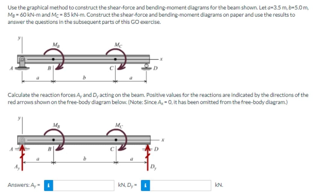
Trending now
This is a popular solution!
Step by step
Solved in 4 steps with 4 images
- Construct the shear force and bending moment diagrams for the beam shown by the area method. Neglect the weight of the beam.For the beam AB shown in Cases 1 and 2, derive and plot expressions for the shear force and bending moment acting on section 1 in terms of the distance x (0 < x< L). [Note: Case 1 results in the conventional V- and M-diagrams, in which the loads are fixed and the location of the section varies; the diagrams for Case 2 (called influence diagrams) show the variation of V and M at a fixed section as the location of the load is varied]Use the graphical method to construct the shear-force and bending-moment diagrams for the beam shown. Let a=3.5 m, b=5.0 m, MB = 110 kN-m and MC = 145 kN-m. Construct the shear-force and bending-moment diagrams on paper and use the results to answer the questions in the subsequent parts of this GO exercise.Calculate the reaction forces Ay and Dy acting on the beam. Positive values for the reactions are indicated by the directions of the red arrows shown on the free-body diagram below. (Note: Since Ax = 0, it has been omitted from the free-body diagram.)Determine the shear force acting at each of the following locations:(a) x = 0+ m (i.e., just to the right of point A)(b) x = 3.5– m (i.e., just to the left of B)(c) x = 3.5+ m (i.e., just to the right of B)(d) x = 12.0– m (i.e., just to the left of D)When entering your answers, use the shear force sign convention.Answers:(a) V = kN.(b) V = kN.(c) V = kN.(d) V = kN.
- Use the graphical method to construct the shear-force and bending-moment diagrams for the beam shown. Let a=3.5 m, b=5.0 m, MB = 110 kN-m and MC = 145 kN-m. Construct the shear-force and bending-moment diagrams on paper and use the results to answer the questions in the subsequent parts of this GO exercise.Calculate the reaction forces Ay and Dy acting on the beam. Positive values for the reactions are indicated by the directions of the red arrows shown on the free-body diagram below. (Note: Since Ax = 0, it has been omitted from the free-body diagram.)Determine the bending moment acting at each of the following locations:(a) x = 3.5– m (i.e., just to the left of B)(b) x = 3.5+ m (i.e., just to the right of B)(c) x = 8.5– m (i.e., just to the left of C)(d) x = 8.5+ m (i.e., just to the right of C)When entering your answers, use the bending moment sign convention.Answers:(a) M = kN-m.(b) M = kN-m.(c) M = kN-m.(d) M = kN-m.Use the graphical method to construct the shear-force and bending-moment diagrams for the beam shown. Let a=3.5 m, b=5.0 m, MB = 110 kN-m and MC = 145 kN-m. Construct the shear-force and bending-moment diagrams on paper and use the results to answer the questions in the subsequent parts of this GO exercise.Calculate the reaction forces Ay and Dy acting on the beam. Positive values for the reactions are indicated by the directions of the red arrows shown on the free-body diagram below. (Note: Since Ax = 0, it has been omitted from the free-body diagram.)Answers: Ay = kN, Dy = kN.Use the graphical method to construct the shear-force and bending-moment diagrams for the beam shown. Let a=3.5 ft, b=9.0 ft, c=4.0 ft, d=3.5 ft, w = 5.5 kips/ft and P = 45 kips. Construct the shear-force and bending-moment diagrams on paper and use the results to answer the questions in the subsequent parts of this GO exercise. For this loading, calculate the reaction forces Ay and Ey acting on the beam. Positive values for the reactions are indicated by the directions of the red arrows shown on the free-body diagram below. (Note: Since Ax = 0, it has been omitted from the free-body diagram.) Ay =___________ kips, Ey = __________ kips. Determine the shear force acting at each of the following locations:(a) x = 0+ ft (i.e., just to the right of support A)(b) x = 3.5 ft(c) x = 12.5 ft(d) x = 16.5– ft (i.e., just to the left of D)(e) x = 16.5+ ft (i.e., just to the right of D)(f) x = 20.0– ft (i.e., just to the left of support E) Answer: a to f ) V = ________ kips Use the graphical…
- Use the graphical method to construct the shear-force and bending-moment diagrams for the beam shown. Let a=4.0 m, b=2.5 m, PB = 4 kN, PC = 4 kN, and MB = 60 kN-m. Construct the shear-force and bending-moment diagrams on paper and use the results to answer the questions in the subsequent parts of this GO exercise.Calculate the reaction forces Ay and MA acting on the beam. Positive values for the reactions are indicated by the directions of the red arrows shown on the free-body diagram below. (Note: Since Ax = 0, it has been omitted from the free-body diagram.) Determine the bending moment acting at each of the following locations:(a) x = 0+ m (i.e., just to the right of fixed support A)(b) x = 4.0– m (i.e., just to the left of B)(c) x = 4.0+ m (i.e., just to the right of B)(d) x = 6.5 mWhen entering your answers, use the bending moment sign convention.Answers:(a) M = kN-m.(b) M = kN-m.(c) M = kN-m.(d) M = kN-m.Use the graphical method to construct the shear-force and bending-moment diagrams for the beam shown. Let a=4.0 m, b=2.5 m, PB = 4 kN, PC = 4 kN, and MB = 60 kN-m. Construct the shear-force and bending-moment diagrams on paper and use the results to answer the questions in the subsequent parts of this GO exercise.Calculate the reaction forces Ay and MA acting on the beam. Positive values for the reactions are indicated by the directions of the red arrows shown on the free-body diagram below. (Note: Since Ax = 0, it has been omitted from the free-body diagram.)Answers: Ay = kN, MA = kN-m.Use the graphical method to construct the shear-force and bending-moment diagrams for the beam shown. Let a=4.0 m, b=2.5 m, PB = 4 kN, PC = 4 kN, and MB = 60 kN-m. Construct the shear-force and bending-moment diagrams on paper and use the results to answer the questions in the subsequent parts of this GO exercise.Calculate the reaction forces Ay and MA acting on the beam. Positive values for the reactions are indicated by the directions of the red arrows shown on the free-body diagram below. (Note: Since Ax = 0, it has been omitted from the free-body diagram.)Answers: Ay = kN, MA = kN-m. Determine the shear force acting at each of the following locations:(a) x = 0+ m (i.e., just to the right of fixed support A)(b) x = 4.0– m (i.e., just to the left of B)(c) x = 4.0+ m (i.e., just to the right of B)(d) x = 6.5– m (i.e., just to the left of C)When entering your answers, use the shear force sign convention.Answer:(a) V = kN.(b) V = kN.(c) V = kN.(d) V = kN.
- For the simply supported beam subjected to the loading shown, derive equations for the shear force V and the bending moment M for any location in the beam. (Place the origin at point A.) Let a=12.0 ft, b=6.5 ft, c= 7.0 ft, w = 7 kips/ft and M = 230 kip-ft. Construct the shear-force and bending-moment diagrams on paper and use the results to answer the questions in the subsequent parts of this GO exercise.Calculate the reaction forces Ay and Cy acting on the beam. Positive values for the reactions are indicated by the directions of the red arrows shown on the free-body diagram below. (Note: Since Ax = 0, it has been omitted from the free-body diagram.) Determine the shear force acting at each of the following locations:(a) x = 0+ ft (i.e., just to the right of support A)(b) x = 12.0 ft (i,e., at point B)(c) x = 18.5- ft (i.e., just to the left of the support C)(d) x = 18.5+ ft (i.e., just to the right of the support (C)(e) x = 24.5 ftNote that x = 0 at support A. Determine the bending…For the simply supported beam subjected to the loading shown, derive equations for the shear force V and the bending moment M for any location in the beam. (Place the origin at point A.) Let a=6.5 ft, b=24.0 ft, P = 32 kips and w = 9.5 kips/ft. Construct the shear-force and bending-moment diagrams on paper and use the results to answer the questions in the subsequent parts of this GO exercise. 1. Calculate the reaction forces Ay and Cy acting on the beam. Positive values for the reactions are indicated by the directions of the red arrows shown on the free-body diagram below. (Note: Since Ax = 0, it has been omitted from the free-body diagram.) 2.Determine the shear force acting at each of the following locations: (in kips)(a) x = 6.5- ft (i.e., just to the left of point B)(b) x = 6.5+ ft (i.e., just to the right of point B)(c) x = 28.5 ft 3.Determine the bending moment acting at each of the following locations: (in kips-ft)(a) x = 6.5 ft (i.e., at point B)(b) x = 28.5 ft 4.Use your…Use the graphical method to construct the shear-force and bending-moment diagrams for the beam shown. Let a=11 ft, b=6 ft and w = 12 kips/ft.Calculate the reaction forces Ay and Cy acting on the beam. Positive values for the reactions are indicated by the directions of the red arrows shown on the free-body diagram below. (Note: Since Ax = 0, it has been omitted from the free-body diagram.)Determine the maximum bending moment that acts anywhere in the beam. When entering your answer, use the bending moment sign convention.Answer: Mmax = Enter your answer in accordance to the question statement kip-ft. Save for Later