Use the virtual work method to determine the slope and deflection at point B of the beam shown


Q: Determine the slope and deflection at point B of the beam shown below by the moment- area method. 90…
A: Young’s modulus of the given beam is E=200 GPa. The moment of inertia of the given beam is I=800×106…
Q: Determine the slope and deflection of the beam at point A in terms of El. Use virtual work method…
A: Given, Total length of beam = 4m Our aim is to calculate, deflection at A using method of virtual…
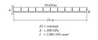
Q: Use the virtual work method to determine the slope and deflection at point B of the beam shown
A: for determining the slope in the beam consider a section and taking moment about the section from…
Q: "| 200 kip-ft 6 ft 18 kips B 9 ft C X
A:
Q: 150 kN C B D - 5 m 5 m - El = constant E = 70 GPa I = 1000 (106) mm4 - 5 m
A:
Q: Use the virtual work method to de termine the deflection at point C of the beam shown.
A: Given Data:Total span L=9mE=constant=70GpaI=500×106mm4Concentrated load = 100kNMoment = 300kN-m…
Q: Use the moment-area method to determine the slope at point A and the deflection at point C of the…
A: Solution: ∑MC=0RA×6-170×3=0RA=85 kNRD+RE=85+70=155…
Q: Use the virtual work method to determine the deflection at point C of the beam shown.
A: In order to find the deflection at point C using virtual work method, we need to formulate the…
Q: 1. By using Conjugate Beam Method, Determine the deflection at the midspan of the beamshown.
A: Conjugate beam: The conjugate beam is described as an imaginary beam with the same dimensions…
Q: For the bears shown below, determine the vertical deflection at poine B by using the virtual work…
A: Given Data:L=20ftpoint load =12kM=70 k-ftto determine vertical deflection:
Q: Use the virtual work method to determine the maximum deflection of the beam shown
A: A beam of length 21ft is given which has support on 0ft (first end) and second support is at…
Q: 3. For the given overhang beam, determine the following using virtual work method. E = 100 GPa and…
A:
Q: M M 3.
A:
Q: Using the virtual work method, compute the slope and deflection at the point B of the beam shown.…
A:
Q: use the virtual work method to determine the deflection at point C of the beam shown
A: Given :- A beam is shown with two point load of 200 kN and 100 kN Modulus of elasticity constant (E)…
Q: to solve for the vertical
A:
Q: Use the virtual work method to determine the slope and deflection at point D of the beam.
A:
Q: B A 1. C
A:
Q: Problem 2: Determine the slope and deflection of the beam at points B and C using Virtual Work…
A: The given beam is shown below:
Q: 4000 mm 150 kN D 4000 mm 3 m 2600 mm B 4000 mm 225 k 3 m- 3 m unu 007
A:
Q: Use the virtual work method to determine the deflection at point C of the beam shown
A: Given:- EI= constant E=29000ksi I=350 in4 To find:- deflection at point C
Q: Use the virtual work method to determine the vertical deflection at joint B of the frame show
A: A frame is given as shown in the figure above and it has been asked in the question to determine the…
Q: Use the virtual work method to determine the vertical deflection at joint B of the frame shown.
A:
Q: Use the virtual work method to determine the horizontal deflection at joint E of the frame shown in…
A: Draw free body diagram of real beam
Q: Use the conjugate-beam method to determine the slope and deflection at point D of the beam shown.
A:
Q: Using Moment-Area Method, determine the slope at A and B and the deflection at point B of the loaded…
A:
Q: Use the virtual work method to determine the vertical deflection at joint B of the frame shown…
A: In virtual method, a unit load is assumed to be acting on the point where displacement has to be…
Q: Determine the horizontal deflection at point b using virtual method
A: Moment of inertia (I) = 832×10-6 m4Elastic modulus (E) = 200 GPa To determine = horizontal…
Q: 50 kN–m LA 4 m- El = constant E =70 GPa I = 164 (106) mm4 %3D %3D
A:
Q: 1. Use the virtual work method to determine the vertical deflection at joint C of the truss shown.…
A:
Q: Use the virtual work method to determine the vertical deflection at joint C of the frame shown
A: Given:- EI=constant E=29000ksi I=2000 in4 load = 2k/ft To find:- Vertical deflection at joint C of…
Q: Use the moment-area method to determine the slopes and deflections at points B and C of the beam…
A: Solution;
Q: Use the moment-area method to determine the slopes and deflections at points B and C of the beam…
A: Write an equilibrium equation for the sum of vertical forces. ∑Fy=0VA+VD=150 kN ...1…
Q: 150 kN-m 50 kN 15 kN/m B C D 6 m 3 m 2 m
A:
Q: Use the virtual work method to determine the horizontal deflection at joint C of the frame shown. 3…
A:
Q: e the moment-area method to determine the slope and deflection at point D of the beam shown.
A: Step: 1 Moment of area method: - It is a method to obtain bending displacements of structures like…
Q: Using the double integration method (DIM), determine the slope at point A and the deflection at…
A:
Q: Determine the slope and deflection at point B of the beam shown by the virtual work method.
A: A loaded beam is given and it has been asked to determine slope and deflection at B using virtual…
Q: Use the virtual work method to determine the vertical deflection at joint C of the frame shown
A: Moment at A:MA=-304.54.52=-303.75KN-m\\Reaction at A:∑ Fy=0Ay-304.5=0Ay=135KnMoment equations:AB:…
Q: Determine the slope and deflection of point C for the cantilever beam shown in Fig. El is constant.…
A: Load at P=20 KN moment diagram
Q: 3. Use the moment-area method to determined the slopes and deflections at points Band C of the beam…
A: SLOPE AT B : AREA OF M/EI DIAGRAM BETWEEN A AND B SLOPE AT C: AREA OF M/EI DIAGRAM BETWEEN A AND C…
Q: Use the virtual work method to determine the slope and deflection at point D of the beam.
A:
Q: Use the virtual work method to determine the horizontal deflection at joint H of the truss shown.…
A: Consider the free body diagram of the truss shown below.
Q: Use the virtual work method to determine the deflection at point C of the beam.
A:
Q: Use the virtual work method to determine the slope and deflection at point B of the beam shown.
A:
Q: Using the virtual work method, compute the slope and deflection at the point B of the beam shown.…
A: Significant models connected with Civil Engineering incorporate structures, scaffolds, and towers;…
Q: Determine the slopes and deflections at points B and D of the beam shown using the Conjugate Beam…
A:
Q: 1) Use the virtual work method to find the deflection at C and OA. 20 k 2 k/ft B 8' 4' 4'
A:
Q: Use the moment-area method to determine the slope and deflections at point B and C of the beam…
A:
Use the virtual work method to determine the slope and deflection at point B of the beam shown.


Trending now
This is a popular solution!

Step by step
Solved in 3 steps with 3 images

- In the cage system below; It is under the effect of a P=250 kN load acting at an angle of θ=75° from the point C. Calculate the horizontal displacement (cm) to the right at point C. (E=2000 kN/cm2 and A=50 cm2 shall be taken for all rods.)In the cage system below; It is under the effect of a P=250 kN load acting at an angle of θ=30° from the point C. Calculate the horizontal displacement (cm) to the right at point C. (E=2000 kN/cm² and A=50 cm² will be taken for all bars.)Questions b and c. The pressure from part a is 0.86832 Mpa
- Determine support reaction at B . Given P=100 Kn L=10 mCompute the value of EIy at 2.5 m from the left support.an open rectangular tank mounted on atruck is 8 m long and 1 m. wide. it is filled with water to a depth of 3.69 meters. if it is accelerated at 10.16 m/s^2 along its length, determine the required height (in meters) of the tank to prevent any water from spiling.
- Water enters the bottom of the cone in Fig. P3.24 at auniformly increasing average velocity V = Kt . If d is verysmall, derive an analytic formula for the water surface rise h ( t )for the condition h = 0 at t = 0. Assume incompressible fl ow.2. A rectangular tank 6m long, 2m wide and 2m deep contains water to a depth of 1m. Itis accelerated horizontally at 2.5 m/s2 in the direction of its length. Determinea) Slope of the free surfaceb) Maximum and minimum pressure intensities at bottomc) Total force due to water acting on each end of tank. Check the difference betweenthese forces by calculating the inertia force of the accelerated mass.Determine the vertical displacement of node A. Consider EA = 16x104 [kN-m]
- 3-15: The unstretched length of a spring AB is 3 m. If the block is held in the equilibrium position shown, determine the mass of the block at D.A pressure of 35 m of head of water is equal a. 34.40 kN/m² b. 343.40 kN/m² O c. 3500 kN/m² d. 3.50 kN/m²The flowrate of the flow is 0.20 + a/10 m3 /s in a pipe placed on a horizontal plane. The pipe diameters are D1= 0.30 m and D2= 0.20. Please find the force acting to the pipe by the flow. The gauge pressure at (1) is p1 =200 + b*10 kN/m2 . (g=9,81 m/s2, g=10kN/m3 ) a= 4 b=3