Using your engineering judgment, critical thinking, and common sense, prepare a process flow diagram in a single sheet of paper that accurately captures the process flow narrative below. You may draw this diagram either by hand or by electronic means. === Two conical storage tanks, with equipment number T-101A and T-101B, contain a mixture of liquid hydrocarbons with pour point of 5°C. T-101A/B operate in a 2 x 100% redundancy. To keep the hydrocarbon mixture homogenized, an internal mixer (M-101A/B) is provided in each tank. The contents of the tank are pumped by centrifugal pumps (P-101A/B/C) via a 10" pipe to another conical storage tank (T-102) 1 kilometer away. The pumps operate in a 3 x 50% redundancy. Assuming the Philippines experiences subzero temperatures 3 months a year, the management has decided to also provide a bypass line. This bypass line, which starts from the P-101A/B/C discharge, diverts the flow to a shell and tube heat exchanger (E-101) where it is heated by hot water (tube-side) to prevent waxing/plugging of the pipes. The heated hydrocarbon mixture connects back to the 10" line and go on its way to T-102. The hot water that goes to the tube-side of E-101 comes from a water storage tank (T-901). Clean water from T- 901 is pumped by P-901A/B (2 x 100%), passes through an electric heater (E-901), and goes into E-101. The hot water cycle is a closed loop system - this means the now cooled water from E-101 is recirculated back to the T-901 to be reused. ===== Notes: 1. There is no need to show instruments or process controls for this exercise. 2. Show only important valves that you think will help the reader understand the process described above. 3. Use the following symbols. a. Shell-and-Tube Heat Exchanger Tube side in C. b. Centrifugal Pump Suction Shell side out Conical Tank Shell side in → Discharge Tube side out e. Mixer M f. Valves g. Pipe 8 M-101A T-101A Closed valve Open valve
Using your engineering judgment, critical thinking, and common sense, prepare a process flow diagram in a single sheet of paper that accurately captures the process flow narrative below. You may draw this diagram either by hand or by electronic means. === Two conical storage tanks, with equipment number T-101A and T-101B, contain a mixture of liquid hydrocarbons with pour point of 5°C. T-101A/B operate in a 2 x 100% redundancy. To keep the hydrocarbon mixture homogenized, an internal mixer (M-101A/B) is provided in each tank. The contents of the tank are pumped by centrifugal pumps (P-101A/B/C) via a 10" pipe to another conical storage tank (T-102) 1 kilometer away. The pumps operate in a 3 x 50% redundancy. Assuming the Philippines experiences subzero temperatures 3 months a year, the management has decided to also provide a bypass line. This bypass line, which starts from the P-101A/B/C discharge, diverts the flow to a shell and tube heat exchanger (E-101) where it is heated by hot water (tube-side) to prevent waxing/plugging of the pipes. The heated hydrocarbon mixture connects back to the 10" line and go on its way to T-102. The hot water that goes to the tube-side of E-101 comes from a water storage tank (T-901). Clean water from T- 901 is pumped by P-901A/B (2 x 100%), passes through an electric heater (E-901), and goes into E-101. The hot water cycle is a closed loop system - this means the now cooled water from E-101 is recirculated back to the T-901 to be reused. ===== Notes: 1. There is no need to show instruments or process controls for this exercise. 2. Show only important valves that you think will help the reader understand the process described above. 3. Use the following symbols. a. Shell-and-Tube Heat Exchanger Tube side in C. b. Centrifugal Pump Suction Shell side out Conical Tank Shell side in → Discharge Tube side out e. Mixer M f. Valves g. Pipe 8 M-101A T-101A Closed valve Open valve

Introduction to Chemical Engineering Thermodynamics
8th Edition
ISBN:9781259696527
Author:J.M. Smith Termodinamica en ingenieria quimica, Hendrick C Van Ness, Michael Abbott, Mark Swihart
Publisher:J.M. Smith Termodinamica en ingenieria quimica, Hendrick C Van Ness, Michael Abbott, Mark Swihart
Chapter1: Introduction
Section: Chapter Questions
Problem 1.1P

Related questions
Question
Transcribed Image Text:6:24
1 of 1
TERM PROJECT
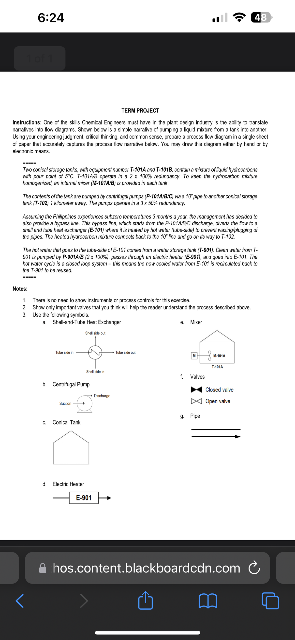
Instructions: One of the skills Chemical Engineers must have in the plant design industry is the ability to translate
narratives into flow diagrams. Shown below is a simple narrative of pumping a liquid mixture from a tank into another.
Using your engineering judgment, critical thinking, and common sense, prepare a process flow diagram in a single sheet
of paper that accurately captures the process flow narrative below. You may draw this diagram either by hand or by
electronic means.
Two conical storage tanks, with equipment number T-101A and T-101B, contain a mixture of liquid hydrocarbons
with pour point of 5°C. T-101A/B operate in a 2 x 100% redundancy. To keep the hydrocarbon mixture
homogenized, an internal mixer (M-101A/B) is provided in each tank.
The contents of the tank are pumped by centrifugal pumps (P-101A/B/C) via a 10" pipe to another conical storage
tank (T-102) 1 kilometer away. The pumps operate in a 3 x 50% redundancy.
Assuming the Philippines experiences subzero temperatures 3 months a year, the management has decided to
also provide a bypass line. This bypass line, which starts from the P-101A/B/C discharge, diverts the flow to a
shell and tube heat exchanger (E-101) where it is heated by hot water (tube-side) to prevent waxing/plugging of
the pipes. The heated hydrocarbon mixture connects back to the 10" line and go on its way to T-102.
The hot water that goes to the tube-side of E-101 comes from a water storage tank (T-901). Clean water from T-
901 is pumped by P-901A/B (2 x 100%), passes through an electric heater (E-901), and goes into E-101. The
hot water cycle is a closed loop system - this means the now cooled water from E-101 is recirculated back to
the T-901 to be reused.
=====
Notes:
1. There is no need to show instruments or process controls for this exercise.
2.
Show only important valves that you think will help the reader understand the process described above.
3. Use the following symbols.
a.
Shell-and-Tube Heat Exchanger
Shell side out
<
Tube side in
b. Centrifugal Pump
Suction
C. Conical Tank
Shell side in
d. Electric Heater
→ Discharge
E-901
Tube side out
e. Mixer
M
f. Valves
48
g. Pipe
M-101A
T-101A
Closed valve
Open valve
hos.content.blackboardcdn.com
Ć
Expert Solution
This question has been solved!
Explore an expertly crafted, step-by-step solution for a thorough understanding of key concepts.

Step by step
Solved in 3 steps with 1 images

Recommended textbooks for you
Introduction to Chemical Engineering Thermodynami…
Chemical Engineering
ISBN:
9781259696527
Author:
J.M. Smith Termodinamica en ingenieria quimica, Hendrick C Van Ness, Michael Abbott, Mark Swihart
Publisher:
McGraw-Hill Education

Elementary Principles of Chemical Processes, Bind…
Chemical Engineering
ISBN:
9781118431221
Author:
Richard M. Felder, Ronald W. Rousseau, Lisa G. Bullard
Publisher:
WILEY

Elements of Chemical Reaction Engineering (5th Ed…
Chemical Engineering
ISBN:
9780133887518
Author:
H. Scott Fogler
Publisher:
Prentice Hall
Introduction to Chemical Engineering Thermodynami…
Chemical Engineering
ISBN:
9781259696527
Author:
J.M. Smith Termodinamica en ingenieria quimica, Hendrick C Van Ness, Michael Abbott, Mark Swihart
Publisher:
McGraw-Hill Education
Elementary Principles of Chemical Processes, Bind…
Chemical Engineering
ISBN:
9781118431221
Author:
Richard M. Felder, Ronald W. Rousseau, Lisa G. Bullard
Publisher:
WILEY
Elements of Chemical Reaction Engineering (5th Ed…
Chemical Engineering
ISBN:
9780133887518
Author:
H. Scott Fogler
Publisher:
Prentice Hall


Industrial Plastics: Theory and Applications
Chemical Engineering
ISBN:
9781285061238
Author:
Lokensgard, Erik
Publisher:
Delmar Cengage Learning

Unit Operations of Chemical Engineering
Chemical Engineering
ISBN:
9780072848236
Author:
Warren McCabe, Julian C. Smith, Peter Harriott
Publisher:
McGraw-Hill Companies, The