VBIAS O- VI O CM 11 M2 M1 RS ∞ www RL CL VO Given values: ID k VTH VA Vov,M₁ Rs RL CM CL 50 μα 1.5 mA/V² 0.60 V 60 V 0.25 V 7.5 ΚΩ 100 ΚΩ 100 pF 10 nF 1. Draw the small-signal equivalent model of the circuit. Assume ro →∞ for both M1 and M2. NOTE: USE THE DERIVED TWO-POR MODEL OF M₁ WITH RS. IN ADDITION, CM AND CL WILL BE INCLUDED IN THE SMALL SIGNAL MODEL. 2. Derive the transfer function(w) and determine the location of the pole and zero frequencies. 3. Determine the gain (in dB) at DC and at the pole and zero frequencies.
VBIAS O- VI O CM 11 M2 M1 RS ∞ www RL CL VO Given values: ID k VTH VA Vov,M₁ Rs RL CM CL 50 μα 1.5 mA/V² 0.60 V 60 V 0.25 V 7.5 ΚΩ 100 ΚΩ 100 pF 10 nF 1. Draw the small-signal equivalent model of the circuit. Assume ro →∞ for both M1 and M2. NOTE: USE THE DERIVED TWO-POR MODEL OF M₁ WITH RS. IN ADDITION, CM AND CL WILL BE INCLUDED IN THE SMALL SIGNAL MODEL. 2. Derive the transfer function(w) and determine the location of the pole and zero frequencies. 3. Determine the gain (in dB) at DC and at the pole and zero frequencies.

Introductory Circuit Analysis (13th Edition)
13th Edition
ISBN:9780133923605
Author:Robert L. Boylestad
Publisher:Robert L. Boylestad
Chapter1: Introduction
Section: Chapter Questions
Problem 1P: Visit your local library (at school or home) and describe the extent to which it provides literature...

Related questions

Question
Is the small signal model of the circuit correct?If yes, proceed in answering the questions; if not, correct the model first, then answer the questions. Note: ignore the parasitic capacitances
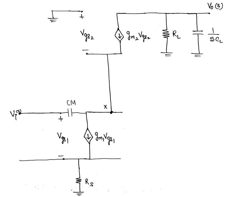
Transcribed Image Text:+
CM
Vgs
+
Vg82
W
X
> gm, Vgs,
Rs
gm₂ Vgsz
Vo (3)
***
R₂
SCL
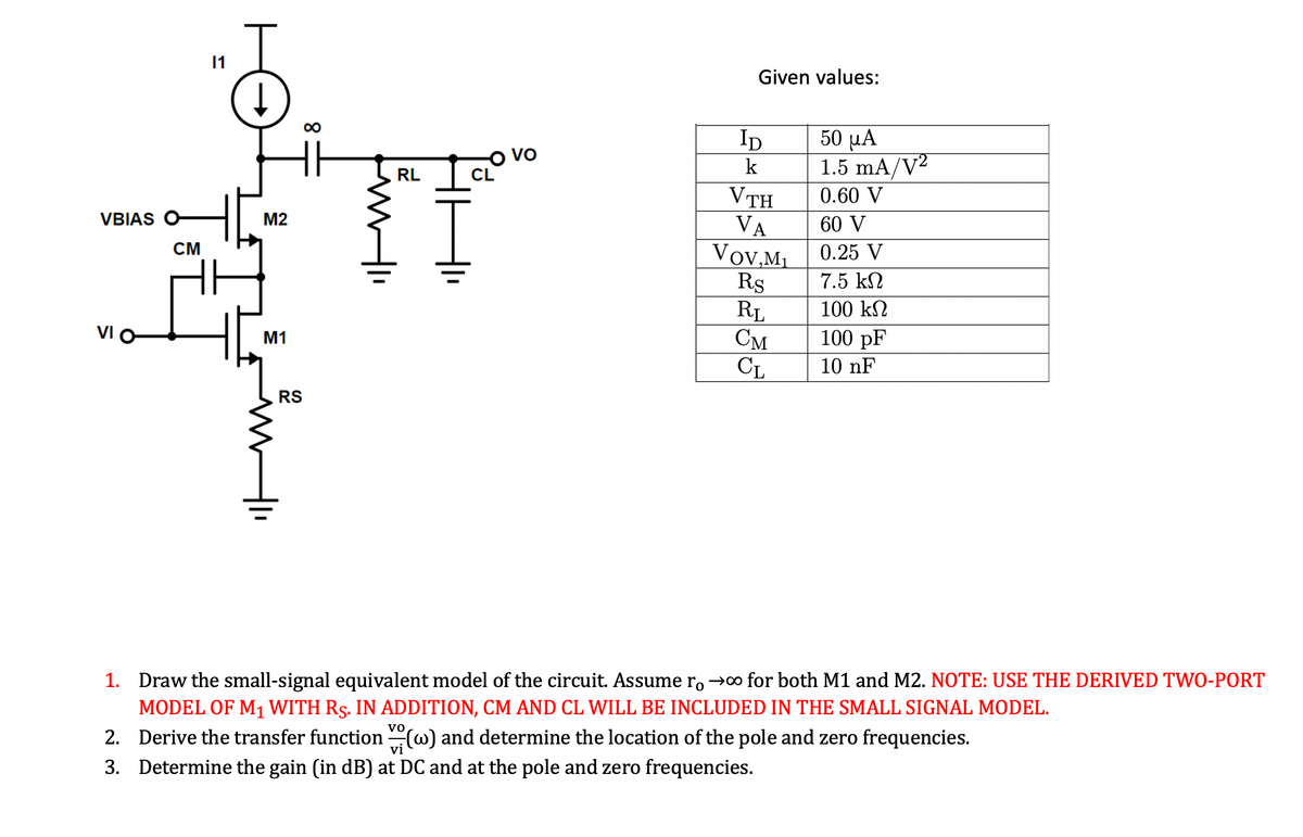
Transcribed Image Text:VBIAS O
VI O
CM
11
M2
M1
MI
RS
www
RL
HH'·
VO
Given values:
ID
k
VTH
VA
Vov,M₁
Rs
RL
CM
CL
50 μα
1.5 mA/V2
0.60 V
60 V
0.25 V
7.5 ΚΩ
100 ΚΩ
100 pF
10 nF
1.
Draw the small-signal equivalent model of the circuit. Assume ro→∞ for both M1 and M2. NOTE: USE THE DERIVED TWO-PORT
MODEL OF M₁ WITH RS. IN ADDITION, CM AND CL WILL BE INCLUDED IN THE SMALL SIGNAL MODEL.
2. Derive the transfer function() and determine the location of the pole and zero frequencies.
3. Determine the gain (in dB) at DC and at the pole and zero frequencies.
Expert Solution
This question has been solved!
Explore an expertly crafted, step-by-step solution for a thorough understanding of key concepts.

Step by step
Solved in 8 steps with 8 images

Knowledge Booster


Learn more about
Need a deep-dive on the concept behind this application? Look no further. Learn more about this topic, electrical-engineering and related others by exploring similar questions and additional content below.Recommended textbooks for you
Introductory Circuit Analysis (13th Edition)
Electrical Engineering
ISBN:
9780133923605
Author:
Robert L. Boylestad
Publisher:
PEARSON

Delmar's Standard Textbook Of Electricity
Electrical Engineering
ISBN:
9781337900348
Author:
Stephen L. Herman
Publisher:
Cengage Learning

Programmable Logic Controllers
Electrical Engineering
ISBN:
9780073373843
Author:
Frank D. Petruzella
Publisher:
McGraw-Hill Education
Introductory Circuit Analysis (13th Edition)
Electrical Engineering
ISBN:
9780133923605
Author:
Robert L. Boylestad
Publisher:
PEARSON
Delmar's Standard Textbook Of Electricity
Electrical Engineering
ISBN:
9781337900348
Author:
Stephen L. Herman
Publisher:
Cengage Learning
Programmable Logic Controllers
Electrical Engineering
ISBN:
9780073373843
Author:
Frank D. Petruzella
Publisher:
McGraw-Hill Education

Fundamentals of Electric Circuits
Electrical Engineering
ISBN:
9780078028229
Author:
Charles K Alexander, Matthew Sadiku
Publisher:
McGraw-Hill Education

Electric Circuits. (11th Edition)
Electrical Engineering
ISBN:
9780134746968
Author:
James W. Nilsson, Susan Riedel
Publisher:
PEARSON

Engineering Electromagnetics
Electrical Engineering
ISBN:
9780078028151
Author:
Hayt, William H. (william Hart), Jr, BUCK, John A.
Publisher:
Mcgraw-hill Education,