Vcc Rc RF2 RF1 C2 C3 Z,

Delmar's Standard Textbook Of Electricity
7th Edition
ISBN:9781337900348
Author:Stephen L. Herman
Publisher:Stephen L. Herman
Chapter30: Dc Motors
Section: Chapter Questions
Problem 6RQ: What is CEMF?

Related questions
Question
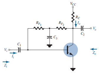
In the circuit in the figure, Vi = 20 mV, VCC = 15 V, β = 110, r0 = 30 kΩ, RC = 4.7 kΩ, RF1 = 100 kΩ, RF2 = 47 kΩ. Also, since the internal resistance of the ac source is RS = 3.92 kΩ and the load connected to the output is RL = 24.5 kΩ, what is the value of the output voltage (V0)?
NOTE: The output impedance of the transistor r0 must be taken into account in the calculations.
Transcribed Image Text:Vcc
Rc
RF2
RF1
C3
Vị o
Expert Solution
This question has been solved!
Explore an expertly crafted, step-by-step solution for a thorough understanding of key concepts.

Step by step
Solved in 2 steps with 1 images

Knowledge Booster


Learn more about
Need a deep-dive on the concept behind this application? Look no further. Learn more about this topic, electrical-engineering and related others by exploring similar questions and additional content below.Recommended textbooks for you
Delmar's Standard Textbook Of Electricity
Electrical Engineering
ISBN:
9781337900348
Author:
Stephen L. Herman
Publisher:
Cengage Learning
Delmar's Standard Textbook Of Electricity
Electrical Engineering
ISBN:
9781337900348
Author:
Stephen L. Herman
Publisher:
Cengage Learning