Vin 2k M + 1k V out VG Assume that the op-amp is ideal. For the transistor M, use K = 2mA/V² and VT = 1V. For the rest of the circuit, use Vin = 2V and VG = 5V. (a) In terms of voltages shown on the diagram, what are VD and V3? Why? (b) Determine Vout and the current flowing out of the output terminal of the op-amp. (c) What mode is the transistor in? Verify that the conditions of that mode are satisfied. (d) Replace the 2kn resistor with a short circuit (wire). 1. Without doing any calculations, what mode you expect the transistor to be in? Why? 2. Show that the transistor is in this mode.
Vin 2k M + 1k V out VG Assume that the op-amp is ideal. For the transistor M, use K = 2mA/V² and VT = 1V. For the rest of the circuit, use Vin = 2V and VG = 5V. (a) In terms of voltages shown on the diagram, what are VD and V3? Why? (b) Determine Vout and the current flowing out of the output terminal of the op-amp. (c) What mode is the transistor in? Verify that the conditions of that mode are satisfied. (d) Replace the 2kn resistor with a short circuit (wire). 1. Without doing any calculations, what mode you expect the transistor to be in? Why? 2. Show that the transistor is in this mode.

Delmar's Standard Textbook Of Electricity
7th Edition
ISBN:9781337900348
Author:Stephen L. Herman
Publisher:Stephen L. Herman
Chapter18: Resistive-inductive Parallel Circuits
Section: Chapter Questions
Problem 13PP: In an R-L parallel circuit, IT=1.25 amps, R=1.2k, and XL=1k. Find IR

Related questions
Question
Transcribed Image Text:2k
M
+
1k
V
out
VG
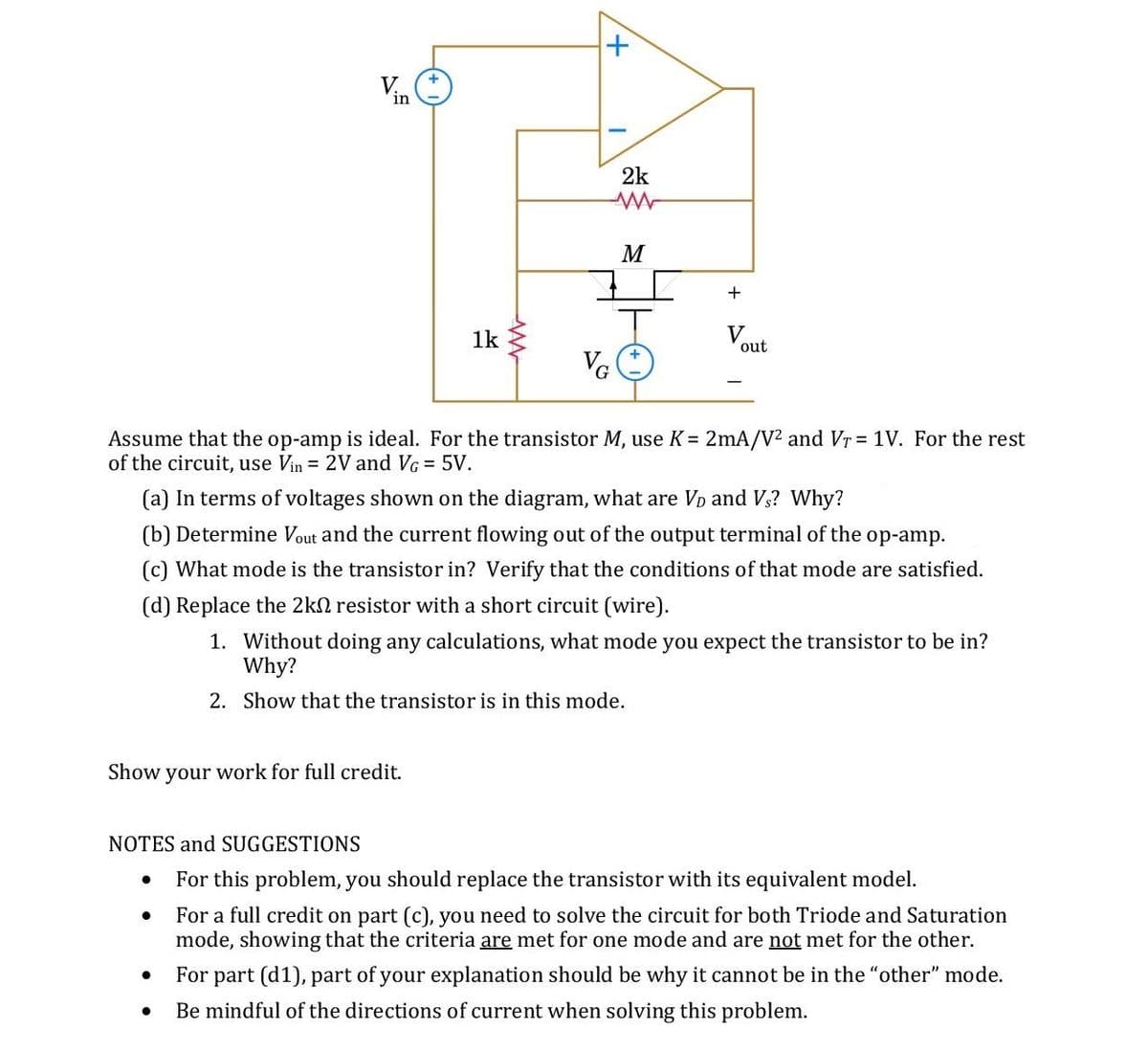
Assume that the op-amp is ideal. For the transistor M, use K = 2mA/V? and Vr = 1V. For the rest
of the circuit, use Vin = 2V and VG = 5V.
(a) In terms of voltages shown on the diagram, what are Vp and V3? Why?
(b) Determine Vout and the current flowing out of the output terminal of the op-amp.
(c) What mode is the transistor in? Verify that the conditions of that mode are satisfied.
(d) Replace the 2kn resistor with a short circuit (wire).
1. Without doing any calculations, what mode you expect the transistor to be in?
Why?
2. Show that the transistor is in this mode.
Show your work for full credit.
NOTES and SUGGESTIONS
For this problem, you should replace the transistor with its equivalent model.
For a full credit on part (c), you need to solve the circuit for both Triode and Saturation
mode, showing that the criteria are met for one mode and are not met for the other.
For part (d1), part of your explanation should be why it cannot be in the "other" mode.
Be mindful of the directions of current when solving this problem.
Expert Solution
This question has been solved!
Explore an expertly crafted, step-by-step solution for a thorough understanding of key concepts.

This is a popular solution!

Trending now
This is a popular solution!

Step by step
Solved in 2 steps

Knowledge Booster


Learn more about
Need a deep-dive on the concept behind this application? Look no further. Learn more about this topic, electrical-engineering and related others by exploring similar questions and additional content below.Recommended textbooks for you
Delmar's Standard Textbook Of Electricity
Electrical Engineering
ISBN:
9781337900348
Author:
Stephen L. Herman
Publisher:
Cengage Learning
Delmar's Standard Textbook Of Electricity
Electrical Engineering
ISBN:
9781337900348
Author:
Stephen L. Herman
Publisher:
Cengage Learning