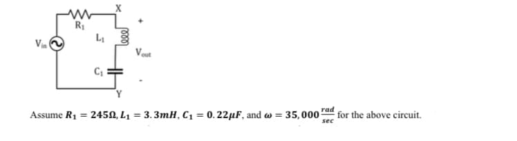
Vin www R₁ L₁ C₁ X 000 Assume R₁ = 24502, L₁ Vout = rad 3.3mH, C₁ = 0.22 μF, and w= 35,000 for the above circuit. sec
Q: 2.5 V + O (a) 2.5 V 2 V (b) 1 V
A: In this MOSFET problem ,we need to find the operating region,where it's cut off , linear or…
Q: Throughout the course of a software development project, a plan will need to be amended several…
A: Throughout the course of a software development project, a plan will need to be amended several…
Q: 2-11 A voltage reading is to be taken across the 6-k2 resistor in the circuit of Fig. 2-36. A…
A:
Q: A shunt motor operates at a flux of 25 mWb per pole, is lap wound and has 2 poles and 360…
A:
Q: In what ways are integrated circuits distinct from transistors
A: Integrated circuits (ICs) and transistors are related in that integrated circuits contain…
Q: Window comparator circuit +Vcc 15 V R1 10K VINO R2 10 K R3 10 K V REF(UPPER) VREFLOWER) + A₁ Az -…
A: In this circuit we have to find the Vref(upper) Circuit:-
Q: For the following circuit, determine by voltage divider the voltage at Zx V=300 sent f = 1kHz M m…
A:
Q: Draw the truth table and logic circuit for a 2-input NOR gate
A: It is given that: 2 input NOR gate
Q: 3. Consider the circuit shown in Figure 2 below. Here, I, = 10-17 A and R₁ = 1 k. Vx T R₁ N D₁ + VD…
A: answer: given that reverse saturation current IS = 10-17 A diode voltage VD =0.8 V resistance R1 =…
Q: .18 The circuit in Fig. P3.18 utilizes three identical diodes aving n=1 and 7, 10" A. Find the value…
A:
Q: Question 24 Determine the current flowing through a 6 mH inductor if the voltage (defined such that…
A: here we have to find the current through the inductor of 6mH.
Q: t = 0. 20 mA 60 kn 100 ΚΩ t = 10 ms + 2 45kΩΣ 1μF7 vc(t) 150 ΚΩ Click to see additional instructions…
A: For the given circuit it is given that the Switch 1 has been closed for a long time while Switch 2…
Q: Problem Imagine that the object is part of a spherical shell. It may be described as 3 ≤ r ≤ 5,60° ≤…
A: Given the object is the part of spherical shell. Given 3≤r≤5,60°≤θ≤90°,45°≤ϕ≤60° To calculate (d)…
Q: 10 cos 21 V 2Η ΤΩ 2 sin 5t A 4Ω www 0.1 F 5 V
A:
Q: 3.7 Assuming that the diodes in the circuits of Fig. P3.7 are ideal, find the values of the labeled…
A: The required parameters can be calculated based on the conduction of both the diodes in the circuit.…
Q: A digital circuit has 14 inputs and 3 outputs. The circuit has 9 registers. How many test patterns…
A: “Since you have asked multiple question, we will solve the first question for you. If you want any…
Q: Q1) Determine the transfer function and the block diagram of the following systems. Explain in…
A: Given, The circuit diagram is shown below,
Q: In the circuits below, R1 = 41 S2, R2 = 71 , R3 = 56 , V1 = 23 V, V2 = -23 V, i1 = -5 A, and i2 =…
A: “Since you have posted multiple questions with multiple sub parts,we will provide the solution only…
Q: certain conductor is composed of strands that are arrangend in 3 layers. Each strand of this…
A: First, we can use the given formula to find the number of strands in the conductor: n = 3x^2 - 3x +…
Q: Find io (t) for t > 0 in the network shown below. 1 = 0 12V(+ ww 6Ω ww 12 Ω 3 Ω id(1) 0.2 Η ww 3 Ω…
A:
Q: B1 Battery Battery E TOP HOH Switch B HOH O HOH UTTU 400
A:
Q: Vin R₁ L₁ C₁ leee Vout Assume R₁ = 2450, L₁ = 3.3mH, C₁ = 0.22μF, and = 35,000 sec for the above…
A:
Q: Problem #8) Determine the Thevenin's Equivalent Circuit parameters (V and R) for the single-port…
A:
Q: V(1) I лиш Ve m = Cs V₂ - с Ls find T-F = Vc(s) VcHH)
A:
Q: A single phase transmission line is delivering 420 KVA load at 10 kV. Its resistance is 70 and…
A: In these questions We need to determine the current through line, sending end voltage, sending end…
Q: 2. Consider the following circuit: R₁ ww Vi(t) V₁(t) il(t) MM Assume the switch is closed at t = 0,…
A:
Q: The following direct-current measurements were made on the two-port network shown in (Figure 1).…
A: Given Data: A two-port network with, Table of values at Port 2 Shorted V2=0 V Table of values at…
Q: Answer letter B. Superposition Theorem. UPVOTE WILL BE GIVEN. ANSWER IN FRACTION FORM.
A: The superposition theorem state that the sum of response of individual sources acting alone is equal…
Q: A neuropathologist is using a device, with a thin circular coil of current-carrying wire of radius…
A: In this question we need to find a induced emf in coil
Q: 1. Draw the positive, negative and zero sequence networks for the power system shown below. Use MVA…
A: In this question we need to draw the positive sequence , negative sequence and zero sequence network…
Q: 6. The switch in the circuit shown below has been closed for a long time and is opened at t = 0.…
A:
Q: A transformer rated 1-kVA, 240/120, 60 Hz. Because of an emergency, the transformer has to be used…
A: Given,The transformer's rating is,1kVA, 240/120, 60Hz.We have to calculate the volt-ampere rating at…
Q: 2. Solve for the transfer function G₁ (s) = = X(S), G₂ (s): G₂(s) = = x2(S), G3(S) F(s) F(s) = = X3…
A: The mechanical modeling of the control system is given as Now, we need to calculate the transfer…
Q: Q2. A Battery of 40 cells is to Be Charged from A 130V supply. The internal resistance of of each…
A:
Q: 1. A 30 MHz plane wave with h=10 sin(wt+ ßx)âmA/m exists in region x20 having σ = 0, ε =25ɛ, µ=4µ.…
A: According to the question, the given EM wave h→ =10sinωt+βxaz^ exist in the region x≥0 having σ=0,…
Q: Construct the circuit in the schematic and complete the accompanying truth table. SV www 1K piscrete…
A:
Q: 1. Consider de signal x(t) = sin wot. Find the complex Fourier series of x(t) and plot its frequency…
A:
Q: For the Figure 6 shown: A 222 -mile long, 47 Hz, three-phase, 3-wire, transmission line is composed…
A:
Q: We can re-write() Therefore, f(x) = f(x) = - n=0 as 2 Σ( (-1)". ( - )" 2 n=0 (-1)^() is equivalent…
A: here we have to re-write the given equations.
Q: For the Figure 1 shown: A 21 -km long, 60 Hz, single-phase, 2-line (line a and line b), transmission…
A:
Q: use superposition to find the Vo. include notes as you solve the problem and box any final answers
A:
Q: 6. The following three-phase, balanced loads are connected across a three-phase, wye-connected…
A: Given that Source is wye-connected, VL=480 V Load 1: Wye connected with 100 kVA at 0.9 pf lagging.…
Q: In regards to semiconductors, how does a diode compare to a transistor?
A: Given: In regards to semiconductors, how does a diode compare to a transistor?
Q: Find the voltage Vz across the Zener diode of Fig. 2-20 (a) if iz= 10mA and it is known that Vz= 5.6…
A:
Q: Problem 2 ( : Apply DeMorgan's theorem to each of the expressions below until primes only appear on…
A: a) Using DeMorgan's theorem: G = (H+ J'K)' = (H)'(J'K)' // distribute the NOT operator over the OR…
Q: With neat block diagram explain the speed measurement system using tacho-generator. 2. Explain the…
A: A tachogenerator is a type of electromechanical device that is commonly used to measure the speed…
Q: Problem #6) Given the Thevenin's Equivalent Circuit for the single-port network shown in the figure…
A:
Q: T Problem #3) Determine the phasor values of the current and the voltage if=13020 volts. Ī…
A:
Q: can you write it more clearly?
A:
Q: Question-2 : Consider the following circuit (assuming the ideal diode model): = VI +1 $45.0 D ich…
A: In an ideal half-wave rectifier, the diode conducts current only during the positive half-cycle of…
Step by step
Solved in 2 steps with 2 images
- Employ phasor-based analysis to obtain an expression for i(t) in the circuit below.The inductance and capacity values used in a transmission path are 20 mH and 60 nF, respectively. Accordingly, find the significant impedance value that will eliminate the delay time per sector of this transmission path and the reflections at its output.Using the diagram capacitor circuit and values provided, find ZC1, Z T, i, VR1, and Vc1
- The characteristic equation of a system is given by S5+2S4+S3+2S2+S+5=0 Determine (i) Stability of the system (ii) Number of roots on the right side of 's' - Plane (iii) Number of roots on the left side of 's' - PlaneA circuit is constructed with an AC generator, a resistor, capacitor and inductor as shown. The generator voltage varies in time as ε =Va - Vb = εmsinωt, where εm = 120 V and ω = 726 radians/second. The values for the remaining circuit components are: R = 62 Ω, L = 95.6 mH, and C = 13.8μF. 4) What is t1, the first time after t = 0 when the voltage across the inductor is zero? 6) What is VC = Vd - Va, the voltage across the capacitor, at time t = 0? Note that VC is a signed number.Consider the circuit diagram below. Compute the impedances for all circuit components, i.e. ??1, ??2, ??3, ??1, ??1, for (a) ? =60 Hz, (b) ?=100 Hz. For both (a) and (b), redraw the circuit diagram with the computed impedances indicated. Express your final answers as a phasors with rectangular coordinates. You must show your all your work for the complex math
- For the circuit shown below, determine:a)The expression of the input current of the circuit in the time and frequency domain, respectively, i(t) and I(s).b)The circuit impedance, Z(s) = V(s)/I(s).c)The stress expression, v(t).d)The currents in the resistor, iR(t), and in the capacitor, iC(t).e)Repeat items c and d if v(0) = – 5 V.A system has the following characteristic equation: s + s + 3 + 2s + 2 = 0 Using the Routh-Hurwitz method, checkA circuit is designed with an AC source of max voltage 12 and frequency 60 Hz. The circuit has a resistance of 1050 Ohms, an inductance of 0.06 Henrys, and a capacitance of 0.009 coulombs per volt. - omega for source in rad/s? - omegaR for circuit? -XL? -XC? -phi in radians? -Z? -imax?
- a series r-c circuit takes a current whose equation is i=0.85sin(754t+pi/4) when connected to a source of emf having the equation e=340sin754t. calculate the capacitance of the capacitor, circuit power factor, and power.For an RC Circuit: a. Using information from the graph, find b. If R= 6982 , calculate C (use the result from Part (a) c. Show, by dimensional analysis, that has units of time.Find the impedance theoretically of a wire if it carries the frequency 10 kHz have a voltage is 8v, the current is 2mA, resistance is 12 kΩ , inductance 27 mH and capacitance 0.2 µf