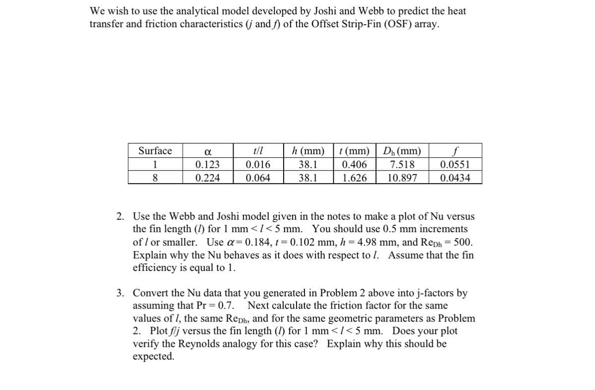
We wish to use the analytical model developed by Joshi and Webb to predict the heat transfer and friction characteristics (j and f) of the Offset Strip-Fin (OSF) array. Surface 1 8 α 0.123 0.224 0.016 0.064 h (mm) 38.1 38.1 t (mm) 0.406 1.626 Dh (mm) 7.518 10.897 0.0551 0.0434
We wish to use the analytical model developed by Joshi and Webb to predict the heat transfer and friction characteristics (j and f) of the Offset Strip-Fin (OSF) array. Surface 1 8 α 0.123 0.224 0.016 0.064 h (mm) 38.1 38.1 t (mm) 0.406 1.626 Dh (mm) 7.518 10.897 0.0551 0.0434

Principles of Heat Transfer (Activate Learning with these NEW titles from Engineering!)
8th Edition
ISBN:9781305387102
Author:Kreith, Frank; Manglik, Raj M.
Publisher:Kreith, Frank; Manglik, Raj M.
Chapter1: Basic Modes Of Heat Transfer
Section: Chapter Questions
Problem 1.15P: 1.15 A thermocouple (0.8-mm-diameter wire) used to measure the temperature of the quiescent gas in a...

Related questions

Question
![S
Lp
Figure 5.7 Unit cell used to derive the Joshi and Webb
[1987] analytical model for the OSF.](/v2/_next/image?url=https%3A%2F%2Fcontent.bartleby.com%2Fqna-images%2Fquestion%2Ff0e69105-edad-4e40-a986-7d2af8f1b9bd%2F2129be97-6632-4773-b11b-907c2aa366dd%2Fk3ka1fq_processed.jpeg&w=3840&q=75)
Transcribed Image Text:S
Lp
Figure 5.7 Unit cell used to derive the Joshi and Webb
[1987] analytical model for the OSF.
Transcribed Image Text:We wish to use the analytical model developed by Joshi and Webb to predict the heat
transfer and friction characteristics (j and f) of the Offset Strip-Fin (OSF) array.
Surface
1
8
α
0.123
0.224
0.016
0.064
h (mm)
38.1
38.1
t (mm) Dh (mm)
0.406
7.518
1.626
10.897
0.0551
0.0434
2. Use the Webb and Joshi model given in the notes to make a plot of Nu versus
the fin length (1) for 1 mm < 1<5 mm. You should use 0.5 mm increments
of 1 or smaller. Use α= 0.184, t = 0.102 mm, h = 4.98 mm, and Reph = 500.
Explain why the Nu behaves as it does with respect to 1. Assume that the fin
efficiency is equal to 1.
3. Convert the Nu data that you generated in Problem 2 above into j-factors by
assuming that Pr = 0.7. Next calculate the friction factor for the same
values of 1, the same Reph, and for the same geometric parameters as Problem
2. Plot flj versus the fin length (1) for 1 mm </<5 mm. Does your plot
verify the Reynolds analogy for this case? Explain why this should be
expected.
Expert Solution
This question has been solved!
Explore an expertly crafted, step-by-step solution for a thorough understanding of key concepts.

Step by step
Solved in 3 steps with 6 images

Knowledge Booster


Learn more about
Need a deep-dive on the concept behind this application? Look no further. Learn more about this topic, mechanical-engineering and related others by exploring similar questions and additional content below.Recommended textbooks for you
Principles of Heat Transfer (Activate Learning wi…
Mechanical Engineering
ISBN:
9781305387102
Author:
Kreith, Frank; Manglik, Raj M.
Publisher:
Cengage Learning
Principles of Heat Transfer (Activate Learning wi…
Mechanical Engineering
ISBN:
9781305387102
Author:
Kreith, Frank; Manglik, Raj M.
Publisher:
Cengage Learning