What does input frequency range and input voltage swing mean? Is it the AC voltage source's frequency and peak voltage?
What does input frequency range and input voltage swing mean? Is it the AC voltage source's frequency and peak voltage?

Power System Analysis and Design (MindTap Course List)
6th Edition
ISBN:9781305632134
Author:J. Duncan Glover, Thomas Overbye, Mulukutla S. Sarma
Publisher:J. Duncan Glover, Thomas Overbye, Mulukutla S. Sarma
Chapter2: Fundamentals
Section: Chapter Questions
Problem 2.2P: Convert the following instantaneous currents to phasors, using cos(t) as the reference. Give your...

Related questions

Question
100%
I'm designing a mixer in Qucs. What does input frequency range and input voltage swing mean? Is it the AC voltage source's frequency and peak voltage?
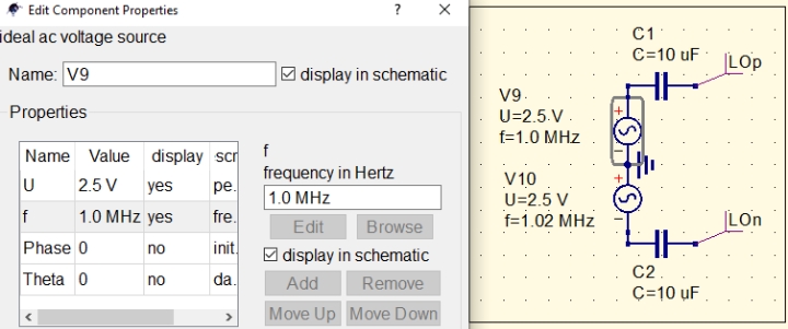
Transcribed Image Text:Edit Component Properties
?
ideal ac voltage source
C1
C=10 uF
Name: V9
display in schematic
LOp
V9.
Properties
U=2.5.V.
f=1.0 MHz
Name Value display scr
f
frequency in Hertz
1.0 MHz
fre.
init,
V10
U=2.5 V
f=1.02 MHz
2.5 V
yes
pe.
f
1.0 MHz yes
Edit
LOn
Browse
Phase 0
Theta 0
no
M display in schematic
da.
C2.
no
Add
Remove
C=10 uF.
Move Up Move Down
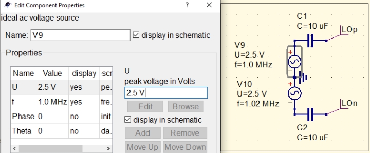
Transcribed Image Text:Edit Component Properties
?
ideal ac voltage source
C1
C=10 uF
LOp
Name: V9
M display in schematic
V9.
Properties
U=2.5.V.
f=1.0 MHz
Name Value display scr
U
peak voltage in Volts
V10
2.5 V
yes
pe.
2.5 V
fre.
U=2.5 V
f
1.0 MHz yes
Lon
f=1.02 MHz
Edit
Browse
Phase 0
init.
no
M display in schematic
C2.
Theta 0
da.
no
Add
Remove
C=10 uF.
Move Up Move Down
>
Expert Solution
This question has been solved!
Explore an expertly crafted, step-by-step solution for a thorough understanding of key concepts.

Step by step
Solved in 2 steps with 2 images

Knowledge Booster


Learn more about
Need a deep-dive on the concept behind this application? Look no further. Learn more about this topic, electrical-engineering and related others by exploring similar questions and additional content below.Recommended textbooks for you
Power System Analysis and Design (MindTap Course …
Electrical Engineering
ISBN:
9781305632134
Author:
J. Duncan Glover, Thomas Overbye, Mulukutla S. Sarma
Publisher:
Cengage Learning
Power System Analysis and Design (MindTap Course …
Electrical Engineering
ISBN:
9781305632134
Author:
J. Duncan Glover, Thomas Overbye, Mulukutla S. Sarma
Publisher:
Cengage Learning