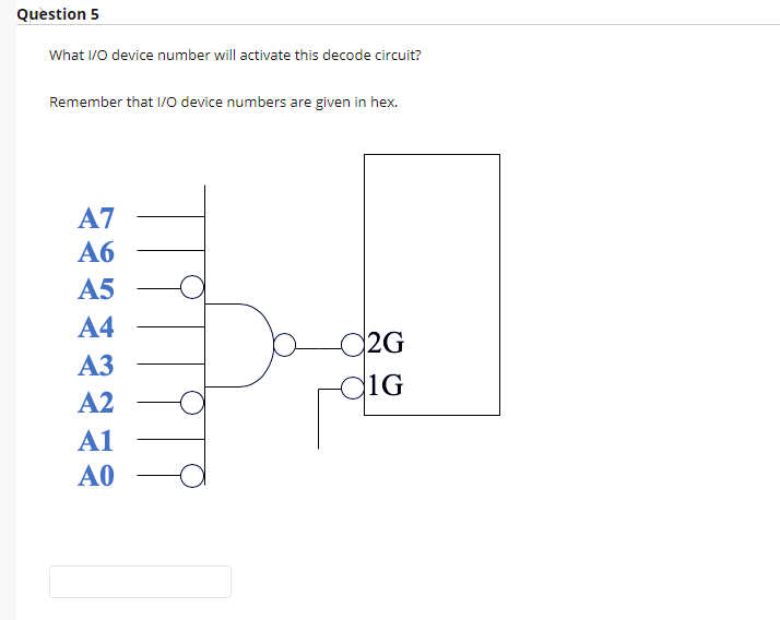
What I/0 device number will activate this decode circuit? Remember that I/o device numbers are given in hex. A7 Аб A5 A4 2G АЗ diG A2 A1 A0


Q: Which of the following is not an IC used inside the ALU? decoder AND gate full adder multiplexer OR…
A: The computer processor (CPU) portion of an arithmetic and logic unit is a part of the arithmetic and…
Q: A 10 bit DAC has a Vref of 5.000 volts. What is 1 LSB or the smallest possible output change on the…
A: Given ==> ADC input = 0 - 5 V ADC output (10 bit) = 0 to 1111111111 in binary = 0 to 1023 in…
Q: out the time-ou TCP timer manag 5.
A:
Q: A crystal frequency of 3 MHz is used for the 8284. What is the clock period (TCLK)? 3 MHz O 10 us O…
A: Option E: 3 μs
Q: The EIA-232 interface has _____ pins. a. 5 b. 15 c. 25 d. 35
A: Given The EIA-232 interface has _____ pins. a. 5 b. 15 c. 25 d. 35
Q: Identify the incorrect statement shown below? O a. Interference signal from one channel to another…
A: The correct option is given in step 2.
Q: What is the value of ALU control lines for NOR operation? 0000 0010 1100 0110
A: Option 1 : 0000 This is ALU control lines for AND operation, so this option is In-correct. Option…
Q: c) Identify the pin configurations of the following decoders. 3-to-8 line decoder (74138 IC) Pin # 9…
A: 1) The IC 74LS138 is a 3 to 8 line decoder, the main function of this IC is to decode and setup of…
Q: How many wires (not including ground) bits? What are these wires for? required for synchronous…
A: The asynchronous communication technique is a transmission technique which is most widely used by…
Q: The period of the FCSR depends on the value of the initial state and the connection taps. * Choose…
A: The answer has given below:
Q: Which of the following combinational circuit is used for data transmission? a. Comparator O b. 7…
A: Combinatorial circuit is a circuit made by combining different logic gates(such as AND, NOT and OR)…
Q: what is the maximum delay that can be generated using 16-bit timer0 with 1:8 prescaling?
A:
Q: Assume LM35 (10 mV/C) is connected to pin A7 of the ADC with VREF = 2.048 volt. Write a program to…
A: GIVEN DATA : Assume LM35 (10 mV/C) is connected to pin A7 of the ADC with VREF = 2.048 volt.Write…
Q: What I/0 device number will activate this decode circuit? Remember that 1/O device numbers are given…
A: Ans -- For activating the decode circuit the inputs will be all hex.
Q: analog value that is connected with IN+ pin of ADC080
A: Q. Write an assembly language program to read the analog value that is connected with IN+ pin of…
Q: Question 1 Q17. Output synchronization between the LC-3 and the monitor takes place by: Your answer:…
A: According to the information given:- We have to choose the correct option to satisfy the statement.
Q: Q1:- An AM wave, calculate the power saving when the carrier and one sideband are suppressed…
A: Given Data:-
Q: The period of the FCSR depends on the value of the initial state and the connection taps. * Choose…
A: The answer has given below:
Q: Compute the time delay generated by an Atmega32 (XTAL = 8MH2) that is programmed by the following…
A: Solution!!
Q: Burst time Process P1 2 P2 18 P3 12 P4 P5
A: Average waiting time using round robin algorithm
Q: 2. Assume you have a button which has to be pressed constantly for 10s. If it is pressed constantly…
A: So here circuit Diagram is given below
Q: output should be taken from the Parity Generator/Checker IC during the read operation to store the…
A: output should be taken from the Parity Generator/Checker IC during the read operation to store the…
Q: Q9/ In a PCM system, the highest frequency component is 10 KHz. The signal is sampled at 40% above…
A: the correct answer is:-
Q: It's difficult to tell the difference between a secret data channel and a hidden timing channel.…
A: Conversion from a timing channel to a storage channel counterpart Per timing channel can be…
Q: (g) In 8051, which bits of the TCON register are function as (i) Start bits of the timers and (ii)…
A: TCON register in 8051 is an 8 bit special function register which is used to control timers…
Q: A list of 5 pulse rates: 70, 64, 80, 74, 92. What is the mean and the median for this list?
A: mean= sum of elements in the list/no. of observation median: arrange the elements in ascending…
Q: UTP is color-coded according to(a) a 10-pair color code (b) a 25-pair color code(c) the resistor…
A: 10-pair color code is not enough to represent all colors of UTP cables Hence, the option (a) is…
Q: How many pins are there in RS-232 D? state the signal group for RS-232 D .
A: Pins in RS-232 D is given below :
Q: Comment on the following line: "Using a 7219 you can drive 64 LEDs while you only need 3 wires to…
A: Given:- "Using a 7219 you can drive 64 LEDs while you only need 3 wires to interface it to a…
Q: There is no need for addressing in synchronous TDM Select one: O True O False
A: Given statement, There is no need for addressing in synchronous TDM.
Q: Based on the Tinkercad circuit accessible from the link below, complete the following activities:…
A: const byte LED_PIN = 13; const byte METER_PIN = A4; void setup() { pinMode(LED_PIN , OUTPUT);…
Q: If each step takes 3nS, then what will be the length of clock cycle?
A: The given question has asked to find the length of clock cycle if each steps takes 3nS.
Q: Help me with the following three questions : 1.How many Analog Input Pinsdoes the Adruino Uno…
A: NOTE:- AS PER OUR POLICY WE CAN SOLVE ONLY ONE QUESTION AT A TIME. SO, PLEASE REPOST THE REST…
Q: Compute the Huffman codes for this source. Compare between the two resu
A: Distinguished source The source of information with an alphabet or a discrete time and amplitude…
Q: alternatives to 7413
A:
Q: The device shown here is most likely a D So EN Select one: O a multiplexer O b. comparator O c…
A: Here in this given circuit we have 1 input line D 2 Select lines S0 and S1 EN which is used to…
Q: A KL25Z GPIO output is used to turn a LED on and off. The cathode of the LED connects to ground and…
A: 1) LEDs have a positive and negative terminal know as the anode and cathode. 2) The cathode of LED…
Q: Build a 2-to-4 decoder with Enable and provide a picture or snapshot of the circuit here. ii)…
A: Below i have given:
Q: output should be taken from the Parity Generator/Checker IC during the read operation to store the…
A: output should be taken from the Parity Generator/Checker IC during the read operation to store the…
Q: a) The value of the current Io b) The power associated to the independent current source. c) Io…
A: the solution :
Q: What are the input and output pins of PORTC if TRISC = 0xNM, where NM are the first two digits of…
A: The Answer start from step-2.
Q: What is the difference between the pins under number 1 and the pins under number 4, and mention when…
A: Arduino required taking an off the shelf microcontroller, using a lot of extra parts, and putting it…
Q: Given the 8MHz oscillator, the timer is set to 8 bits with Prescaler 2 and preload
A: Given that frequency of oscillator (f) = 8 MHz = 8 * 10⁶ Hz Here the timer used is 8 bits. Hence the…
Q: Which type of filter is used to turn a PWM signal into an analog voltage? OI t depends on the PWM…
A: c) Low pass filter
Q: An AM modulator has the output SAM (t) = Accos(2n100t) + 5cos(2n40t) + 5cos(2n60t) and modulation…
A: Given Ac=? Modulation index = 0.4
Q: Which one of the following is a device commonly used in electronic prototyping? a. Solderless Packet…
A: PCB mechanically supports and electrically attaches various components using various types of…
Q: Define rotational latency.
A: Rotational latency Rotational latency is the time taken for a specific block of data on a data…
Q: F (A, B, C, D) = A'B + C'D + AD . What is the type of the decoder? (Example. 3-8 active high…
A: Decoder is a combinational logic circuit that converts coded input to coded outputs provided both of…
Q: A decoder is activating only the output that corresponds to the input number, all other outputs…
A: lets understand decoder and control unit: Decoder: It is Combinational logic circuit, which takes n…
Q: Based on the Tinkercad circuit accessible from the link below, complete the following activities:…
A: Answer. Step 1 const byte LED_PIN = 13; const byte METER_PIN = A4; void setup() { pinMode(LED_PIN…


Step by step
Solved in 2 steps with 1 images


- Using the tiva c tm4c123 write an interrupt function for switch 1 in which when switch 1 is pressed, it turns on the RED LED (PF1) by sending a character R to a Bluetooth Hc05 module which in turn, turns on PF1, and when it is not pressed LED is off. please write code in cUsing the sim8085 write the following code: In a sensor network, three pressure sensors are connected which gives the reading of 4 psi, 8 psi and 10 psi. All the sensor readings are to be summed up and store as a single readingYou manager has asked you to write a report to a customer who will be using the following digital circuits that implement combinational circuits in their operation: A one bit, 3 input majority counter (voter)Please Include a analyze of the contruction and operation of the circuit how it works in simple steps Truth table and Boolean Algebra/Karnaugh
- Comment on the following line: "Using a 7219 you can drive 64 LEDs while you only need 3 wires to interface it to a microcontroller"3. Equipment that uses RS 232 cables typically connects to a 9 pin port on a PC.The above statement is: a. TRUE b. FALSEHelp me with the following three questions : 1.How many Analog Input Pinsdoes the Adruino Uno have? 2.How much SRAM does the Adruino Uno have? 3.What will the value of the solution variable be after the code segment below has been run. int solution = 91; int number53 = 17, number11 = 8; solution -= number53 * number11 ;
- Based on the Tinkercad circuit accessible from the link below, complete the following activities:https://www.tinkercad.com/things/c1qtxCkOuBW Code is, // C++ code// const byte LED_PIN = 13;const byte METER_PIN = A4; void setup(){ pinMode(LED_PIN, OUTPUT); pinMode(METER_PIN, INPUT); Serial.begin(9600); startTimer();} void loop(){ } void startTimer(){ noInterrupts(); interrupts();} ISR(TIMER1_COMPA_vect){ digitalWrite(LED_PIN, digitalRead(LED_PIN) ^ 1);} 1. Complete the code in a way that LED blinks every 2 seconds.2. Change the startTimer method to accept a double value called timerFrequency, which representsthe frequency of the timer. Change the startTimer function so that it uses the value of this parameterto calculate and set the correct values for the OCRx and TCCRx registers.3. Use the potentiometer sensor connect to pin A4 to enable users to configure the timer frequencyBased on the Tinkercad circuit accessible from the link below, complete the following activities:https://www.tinkercad.com/things/c1qtxCkOuBW Code is, // C++ code// const byte LED_PIN = 13;const byte METER_PIN = A4; void setup(){ pinMode(LED_PIN, OUTPUT); pinMode(METER_PIN, INPUT); Serial.begin(9600); startTimer();} void loop(){ } void startTimer(){ noInterrupts(); interrupts();} ISR(TIMER1_COMPA_vect){ digitalWrite(LED_PIN, digitalRead(LED_PIN) ^ 1);} 1. Complete the code in a way that LED blinks every 2 seconds.2. Change the startTimer method to accept a double value called timerFrequency, which representsthe frequency of the timer. Change the startTimer function so that it uses the value of this parameterto calculate and set the correct values for the OCRx and TCCRx registers.3. Use the potentiometer sensor connect to pin A4 to enable users to configure the timer frequency. Plsease share the final code only.Suppose you would like to connect an LCD Display to an Arduino Uno in Half-Byte mode c) Demonstrate the connections and explain the purpose of each pin. Also write in short, the method of how data is transferred in contrast to the conventional Full-byte mode. d) Explain how you can interface an 8X8 LED display with an interfacing IC and a helper IC such as the Johnson counter. Write a short note on it.
- You have an AVR ATmega16 microcontroller, one yellow LED, and one bicolor LED. Write a program to make the yellow LED (connected at I/O pin PD2) blink on and off once every second for three seconds. Then, the bicolor LED starts green for 500 ms (connected at I/O pin PB1) and then changes the bicolor LED to red (connected at I/O pin PB0) for 500 ms. After that, the yellow LED will switch back on and stay that way. Also, draw the schematic diagram for the circuit. 30 minutes thumbs up like.You have an AVR ATmega16 microcontroller, one yellow LED, and one bicolor LED. Write aprogram to make the bicolor LED start out green for 3 seconds (connected at I/O pin PB0). After 3seconds, change the bicolor LED to red (connected at I/O pin PB1). When the bicolor LED changesto green, flash the yellow LED (connected at I/O pin PB2) on and off once every second for tenseconds. When the yellow LED is done flashing, the bicolor LED should switch back to red andstay that way.Given the 8MHz oscillator, the timer is set to 8 bits with Prescaler 2 and preload 6. How long does it take for the timer to raise its flag? (ms)