What is current I2


Q: Calculate voltages V1, V2, and V3 4 V 4V 6 V 12 V
A:
Q: ind I3 in the circuit below. Use units (A), please.
A: Kirchhoffs Voltage Law or KVL, states that “in any closed loop network, the total voltage around the…
Q: What is current i2
A: Using ohms law and KCL to find node voltage Vab and than using vab we will find current i2. By ohms…
Q: 3. b) Determine Is , I1, I2 and Va, VB, Vc. Explain the answers in your own words. [3] + VA - 4Ω 10…
A: To solve above problem, we will use Ohm's law and Kirchhoff's law: Ohm's law state that in a current…
Q: The algebraic sum of voltages around any closed path in a network is equal to ____________ a)…
A: According to Kirchhoff's voltage law (KVL) the algebraic sum of the voltage differences around any…
Q: 10 V i1 13 10 V i2
A:
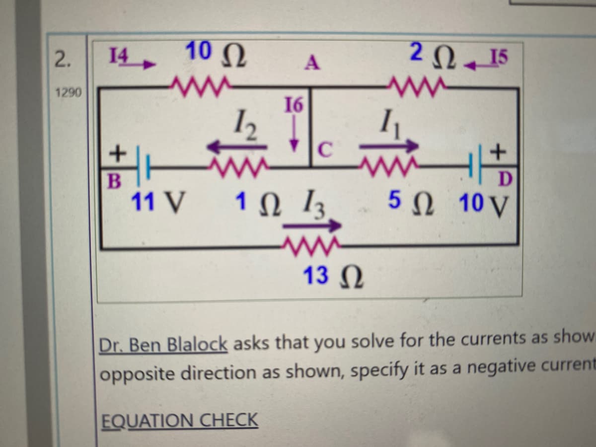
Q: Q2. Find all the branch currents. Io 9Ω I4 36 V v(+ I2 12 N 18 Ω Ιs
A: On redrawing the circuit, the circuit will look like, To calculate the branch currents we will use…
Q: the voltage across R2 is _______ i2.
A:
Q: Kirchhoff's voltage law (KVL) states that the sum of all voltages in a circuit equals zero. Select…
A: Need to find true false
Q: Kirchhoff's voltage law (KVL) states that the sum of all voltages around any path in a circuit…
A: Choose the correct options The given statment What is KVL law
Q: V. Lo I V2 4 kN 2 kN 2 k2 V out 3 ΚΩ 12 V
A: Given circuit:
Q: Determine I1, I2, Vo and V₁. Figure 1
A: As per the guidelines,we are supposed to answer only first question. Please repost the remaining as…
Q: 3 2 + V2 is v5 70 24 V + Vi
A: We need to find out current and voltage and power for given circuit
Q: Simılarly, the current flowing through the R2 can R1 12 = Is R1+ R2 S %3D Procedure: Part 1: Voltage…
A: The solution can be achieved as follows.
Q: Problem 2 Find V₂ (t) for all time t. 4 V ΖΩ ww 15 t = 0 t = 0 2 H + VR202
A: In this question, We need to determine the voltage across the resistance R= 2 ohm We are solving…
Q: 1.W ind the currents /1 and 12 and the voltages V, and V; for the network R1 R3 L2 R4 R2 R5 E 50 V
A:
Q: Calculate the voltages at points a and b and the currents I1, I2 and I3. what is the power in the…
A: For the given circuit we have to Calculate the voltages at points a and b and the currents I1, I2…
Q: 15iz (V) 11 10 V
A:
Q: The answer is 60ohm. However i could only get 40 ohms using the method shown below. R1 // R2+R3…
A: The correct answer is 60 ohm. detail solutions is in the image
Q: what is the state space for this system? 1 T(s) s3 + 8s2 + 13s+ 6
A:
Q: ) Compute Vo: ot 2mA V. SHK2 14mA
A: PRESENCE OF SOURCE: In the presence of sources, all the passive elements which are R, L and C always…
Q: 12 + E - 12 * 20 V = 3.32 mA 3.12 mA 3.55 mA O 3.97 MA Si ✈ D₁ R₂ 5.6 ΚΩ Si D₂ 10₂ R₁ 3.3k92 I₁
A:
Q: ElectricalEngine www.electricalengir 10 V- Current flowing through the circuit is: a) 10 A b) d) 50…
A: we need to determine value of current.
Q: What is the value of I2
A:
Q: Consider the circuit shown below. The voltage across R1 is Blank 1 V. 1 R1 V1 1 20V 5A 102 2 Blank 1…
A:
Q: i literally said the no.3 not no.1
A: The inverting amplifier can be designed by using the tinkercad software.
Q: Current flowing throught the circuit can be expressed as a) (R1/(R1 + R2) x 1 b) vs/R2 c) all of…
A: The two resistance are in parallel. And by total current shared by them is I. Current division…
Q: What is the value of the Current I1, I2, I3
A:
Q: t-0 R1 R2 V=30 V, R1=200 Ohms, R2=100 Ohms, L=0.2 H.
A:
Q: FIGURE 2 R +8 v- 8 us 12 us 4 us -8 V
A: An OPAMP (operational amplifier) is an integrated electronic circuit that is used to amplify weak…
Q: I. Determine the voltage V1. II. Determine the currents I1 and I2. 102 12 V1 20V 10N b 11
A: Nodal analysis is an important method to solve big and complex circuits. It is based on Kirchoff's…
Q: PLEASE SHOW YOUR SOLUTION ON A PAPER The i1 is at the 6 ohms and the i2 is at the 8 ohms.
A: In this question , we will find current through 6 ohm and 8 ohm.....
Q: Calculate the currents I₁, I2, and I3 in the circuit given in Figure 1(b). R₁ www 202 I = 12 A 12 R₂…
A: Given circuit,
Q: by kirchhoff find i1,i1,i3 and voltage at any resistance 1002 R. 5V
A:
Q: R1 R2 Vs D1 Io R1 Voltage Value Passives Value @ 21 °C R R2 Vp R3 Vs 12 V 0.00386 3.3 kN -0.0005 0.7…
A: Solution- Given data,Vs=12VI=3.381mAAt 21°C,R1 = 5Ω, α=0.00386R2=3.3Ω, α=-0.0005R3=5Ω,…
Q: I. Determine the voltage V1. II. Determine the currents Iı and I2. 62 102 12 V1 20V 102 b 11
A: Nodal analysis is an important method to solve big and complex circuits. It is based on Kirchoff's…
Q: Calculate the Id1 and Id2 currents in the given figure
A: It is given that:
Q: The ammeter shown in the figure below reads 2.68 A. Find I1, I2, and E. %3D A. I2 A V = 3
A: The required values can be calculated by using kirchhoff's law and ohms law.
Q: Find the currents in the circuit. 5 V 5Ω I1 I2 102 I3 10 V
A: Please refer the attached images for the complete answer..
Q: For the circuit shown in the figure below, the value of currents 1₁ and 12 is: |I₁ R₁ = 300 R₂ = 600…
A: Given circuit,
Q: س4 : جد قيمة المقاومة R بطريقة مجزيء التيار . It=27mA 12 I1=21mA R2 =7 2 R1
A: Note : as per guideline we have solved question at a time please repost remaining questuon
Q: 1002 Re 503 152
A:
Q: +18V
A: From the basic circuit analysis
Q: Solve for I. + 5 V 7.5 kN 2.2 k2 1 k2 Si
A: In this question, We need to find the current I as shown in the circuit. Assume forward bias…
Q: 5. Calculate all unknowns for the following circuit. + V₁ - W R₁-201 20 V Ry R₁-25 12 www R₂ ISAV,…
A:
Q: Determine current I3 and I1 (in Amperes) in the circuit below.
A:
Q: 20 40Ω in iz 1250 500 2400 200 120mA >
A:
Q: Use ohm's law and please show complete solutions
A:

Step by step
Solved in 2 steps with 2 images

- Given the circuit shown below, if Zx = 100/0 o determine the current in each branch by: a) Nodal Methodb) Maxwell’sMethodCompute for IN, RN and the current passing though the 25-ohm resistor using Norton’s Theorem. Answer neatly and please explaiin the processWrite the differential equation for t > 0 for iC in the given figure. Assume VS = 9 V, RS = 4 kohm, R1 = 11 kohm, and R2 = R3 = 20 kohm.
- Find the value of Z in the circuit seen in figure if Vg= 50–j100 V, Ig= 20 –j30 A, and V1=100 + j50 V.Use the node-voltage method to find the steady-state expression for io in the circuit seen in (Figure 1) if ig= 4 cos2500t A and vg= 16 cos(2500t+90∘) V. Write the steady-state expression for io(t) as io=Iocos(ωt+ϕ), where −180∘<ϕ≤180. Find the numerical value of Io. Find the numerical value of ϕ.QA) The apparent power for an electric network was measured and found to be 360.6VAZ-56.34% 1. Determine the power factor of the network and sketch the power triangle. 2. Identify the elements of the network and provide a reason justifying your answer. B) Define the permeability (ur) of the material. If you are required to design IH and I uH inductors, what type of core will you use in your design and why? support your answer by equations.
- Understand ac power concepts, their relationships to one another, and how to calculate them in a circuit Find the phasor voltage Vs in the circuit shown if loads L1 and L2are absorbing 15 kVA at 0.6 pf lagging and 6 kVA at 0.8 pf leading,respectively. Express Vs in polar form.Find steady -state expression of current Io using mesh analysis. Answer is io = 2.532 cos (40000t+161.560^deg ) AFind the mesh currents in steady state whenVf = 10√2cos (ωt + 45˚) V and If = 3cos ωt A Sol.I1=8.25cos(ωt+76˚)A
- The curve is described by V(t)=Vm*cos(w*t+theta) + Vshift. Given V1= 1 volts, V2=-V1, V3=0.2450 volts, and T=9.500 msec. Find Vm (volts), w (rad/sec), t3 (msec), theta (deg), and vshift (volts).Sketch V0 for the networkAnswer the following points in detail and rigorously. Instead of resorting to formulas, develop from basic principles (laws of voltages and currents, definition of electrical power, properties of phasors, among others). a) Suppose that between the two terminals of an element there is a voltage v (t) and that a current i (t) enters through the terminal marked with a positive sign. Show that if v (t) and i (t) are sinusoidal and are out of phase by an angle ϕ, then the active power P that is consumed by said element is proportional to cos ϕ. b) How much is P for a pure inductor and how much for a pure capacitor? Does this make physical sense? c) When specifying the power factor seen between two terminals, why is it necessary to indicate whether it is lagging or leading? d) Show that the complex power consumed by two elements in parallel is the sum of the individual complex powers. Then repeat the procedure but for two elements in series. e) What meaning would you give to the P consumed…