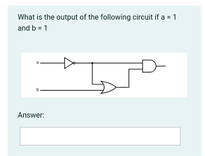
What is the output of the following circuit if a = 1 and b = 1 Answer:


Q: 2. For each of the following circuits, write a truth table tabulating the circuit's output for each…
A: Truth table is a logical table in which we gave input and then we get output. A truth table is a…
Q: For the circuit in the figure, indicate the value of Q at time T1 1 INDETERMINATE 0
A: For the circuit in the figure, indicate the value of Q at time T1 1 INDETERMINATE 0
Q: 3. [Score 15) Draw the combinational circuit for the following Boolean expression: (X +Y)(X + Z)(X +…
A: Combinational circuit is a circuit in which we combine the different logic gates in the circuit−…
Q: For the following circuit Do a. Write the output expression. b. Implement the logic circuit using…
A: a. In the given logic circuit, A, B, and C are the inputs and X is the output. A and B are the…
Q: Show the behaviour of the circuit below using a Truth table
A: We are given a circuit and we are going to draw truth table for circuit expression. Please refer to…
Q: or the given circuit, what will be the value stored in 6-
A: Q
Q: Draw the combinational circuit that directly implements the above Boolean expression.
A:
Q: Write the Boolean equations and draw the logic diagram of the circuit whose outputs are defined by…
A:
Q: Q1- Combinational circuit is the type of circuit where output not only relies on the input but also…
A: Combinational circuit is the circuit, it is the combination of two or more circuits. Examples of…
Q: A Q D Q Y K Q' Q' B.
A: Sequential circuit: In sequential circuit, the external output of a circuit depends on the external…
Q: Given the below Function: F(x, y, z) = (x + y). (y + z) + xyz a- Draw the combinational circuit that…
A: Solution :
Q: Find the Boolean expression of the following circuit, draw the circuit on EWB and simulate it to…
A:
Q: Write Boolean expressions for the circuits given below
A: The given diagram is a 3 variable function with inputs as function of A, B and C and output as Q.
Q: What Boolean function does the following circuit represent? A Y
A: Given The circuit
Q: Draw a circuit that uses only one AND gate and one OR gate to realize the following function: F(a,…
A: A logic gate is an idealized or physical device implementing a Boolean function, a logical operation…
Q: Given the below Function: F(X, y, z) = (x + y). (y + z) + xyz a- Draw the combinational circuit that…
A: answer is given below:
Q: W Y X Y
A:
Q: Siven the following circuit and assuming that =1, B=0, C=1, what are the values of sum, arry, and Y…
A: Here A=1 and B=0 , this means input I2 will be available at the output Y.
Q: Write the Boolean equations and draw the logic diagram of the circuit whose outputs are defined by…
A: First we have to write the f1 and f2 to get the boolean equation. For that, wherever the value is 1…
Q: A combinational circuit has 3 inputs A, B, C and output F. F is true for following input…
A: Answer :- Option A) F = A’ +BC
Q: Complete the following characteristic table for the circuit below: You need explain how you got the…
A: In this question, we have a synchronous sequential circuit. And we have some values at clock 't' and…
Q: P AND NOT AND OR R
A:
Q: Build a circuit that has the same behavior as a nand gate (i.e. for the same inputs, gives identical…
A: the python program is an given below :
Q: Q1:For the following circuit find voltage gain, current gain input impedance ,output impedance…
A: Answer :-
Q: Question 2: For the circuit shown below, assume that Q = 0, Q; = 0, Q +1 = 1, D, = 1. Complete the…
A: I0=Qi=0 I1=Qi-1=0 I2=Qi+1=1 I3=Di=1
Q: What is the value at output O of the circuit below when x= 0, y=1?
A: The given diagram shows a logic circuit which is a combination of OR, AND and OR logic gates. The…
Q: Evaluate the circuit below for the inputs: A: 1, B: 1, CO
A: The inputs are A=1, B=1, C=0 Let's number the gates from top to bottom The NOT gate at top is…
Q: Convert the circuit below to the one using only two-input NOR gates. Then write the output…
A: The output of given circuit(old circuit) is: (A'+B')'.BC
Q: Design a combinational circuit with three inputs, x, y, and z, and three outputs. A. B, and C by…
A: Truth Table X Y Z A B C 0 0 0 0 0 1 0 0 1 0 1 0 0 1 0 0 1 1 0 1 1 1 0 0 1 0 0 0 1 1 1…
Q: (a) Find the output of the circuit corresponding to the input P = 1, Q = 0, and R = 1. (b) Write…
A: A boolean expression is a logical statement that is either true or false .
Q: For the circuit in the figure, indicate the value of Q at time T3 0 INDETERMINATE 1
A: Dear Student, As EN is in 0 during T3 and anything AND with 0 is 0 and not of 0 is 1 ie NAND input…
Q: Q. For the given circuit, which of the following is correct?
A: ANSWER : Option C is correct. Explanation : EN is at active low means it is active when 0 is given…
Q: Determine the value of X and Y in the below given circuit implementation of function F(A, B, C) =…
A: Introduction
Q: In the following circuit implementation, what is the correct expression of f and g?
A: For the given circuit we have 3 inputs a, b, and c, that give following output combinations.…
Q: Build the circuit shown below and complete the truth table to show correct operation. Input A Input…
A: Equation for A<B: F = A'B Truth table for A<B: A B A' Output 0 0 1 0 0 1 1 1 1 0 0 0…
Q: Design a combinational circuit for four inputs in a way that if the input is less than 8, output…
A:
Q: Analyze the following combinational circuits by showing its Boolean function
A: Here in this question we have given a combinational circuit and we have asked to simplify and…
Q: The circuit has 2 flip-flops, A and B, two inputs (X and Y) and one output Z. The output of F.F. A,…
A: Solution
Q: For the circuit shown below the output F is given by X- F O F = 1 O F = 0 O F = X O F = M|
A: Explanation : At, first Xor gate X and X are entered so, 0 will come out. At, Second Xor gate X…
Q: Are the following two logic circuits equivalent and write the final equation for the circuits:- * B…
A: a) AB + CD
Q: WHAT IS THE CIRCUIT FOR THE BELOW LOGIC GATE Y = ( K' M)' + K ( P + F)
A: The given logic function is; Y = (K' . M)' + K . (P+F) where, Y is the output, K,M,P,F are the…
Q: Draw a circuit that uses only one AND gate and one OR gate
A: AND circuits takes two inputs and produces an output and it is 1 only if both inputs are 1 OR…
Q: Question 8: Draw the circuit that implements each of the following equations: B + AC' (W + Y)' + X'…
A: Objective: Boolean equations can be expressed through digital circuits and gates (AND, OR, NOT).…
Q: The circuit below acts as a J Q K CLK
A: Solution: D Flip Flop has One input i.e., D(Data) but here we have two inputs j and k so Option c is…
Q: Please see question attached.
A: The given expression have following gates:An AND gate between B, C and A with a NOT gate.An XOR gate…
Q: Q1. Write the expression and show the behavior of the following circuit with a truth table (3.5…
A: EXPRESSION: The AND gate is performed between the input A and B. The NOR gate is performed between…
Q: 3. Build a circuit using AND, OR, and NOT gates to implement the following truth table. b Output a C…
A: Designed circuit using given truth table
Q: From the given choices find the Boolean expression of the Logic circuit: ABC
A: first gate is AND gate so f1=AB'C (because B contain NOT gate) second gate is also AND gate so…
Q: Given the truth table as in Table Q3, draw the simplified logic circuit using K-Map. b) Table Q3…
A: k-map: The k-map was intoduced Maurice Karnaugh in 1953 .The k-map stands for karnaugh map.The…
Q: Find the output of the combinatorial circuit below. r p
A: Final output is (Not r + p not q) *( not p)


Trending now
This is a popular solution!

Step by step
Solved in 2 steps with 4 images


- Design the simplest circuit that has three inputs, a, b, and c, which returns an output value of 1 whenever g and b are complements of each other or b and c are complements of each other, otherwise the output is 0. Realize the circuit using 4input , 3output PALimplement the following circuit. Write the boolean expression describing its outputsDesign a circuit that compares two 3-bit numbers A and B to check if they are equal and less than. The circuit has two outputs X and Y, So that X=1 if A==B and X=0 if A!=B and Y=1 if A<B and Y=0 if A>B
- Design a combinational circuit with three inputs x, y, and z, and three outputs, A, B, and C. When the binary input is 0, 1, 2, or 3, the binary output is one greater than the input. For example, if the inputs are 000, the outputs are 001. When the binary input is 4, 5, 6, or 7, the binary output is two less than the input. For example, when inputs are100, the outputs are 010. Show the truth table for the inputs and outputs. please show all steps , dont just explainIn what kind of circuit is it possible to select binary information from a great number of input lines and then send that information to a single output line?What the out should be for the circuit below
- Need correct answer only upvote otherwise downvotes more and more Circuit implementedDesign a combinational circuit that accepts a 4-bit number and generates abinary number output that approximates the square root of the number. Forexample, if the square root is 3.5 or larger, give a result of 4. If the squareroot is <3.5 and >= 2.5, give a result of 3. Use K-maps to simplify the circuit.Draw the circuit.Design a calculator to calculate the sum and difference of unsigned two numbers. At this time, the total and tea can be included in the same circuit or they can be separated.
- Convert the following a sequential circuit in piplined design Please answer the question as soon as possible ThanksGiven a 4-bit signed integer, design a circuit that outputs its absolute value. You can assume that the input will always have a valid output. (a) Draw a logic diagram of this circuit. You may use 4-bit half adder(s), 2x1 4-bit multiplexer(s), and any logic gate(s) in your design. (b) With the following Verilog code, implement your design above in Verilog. module half_adder (input [3:0] a, input [3:0] b, output [3:0] s); assign s = a + b; endmodule module mux(input [3:0] D0, input [3:0] D1, input S, output reg [3:0] O); always @(*) begin if (S == 0) O = D0; else if (S == 1) O = D1; else O = 4’bx; end endmoduleDraw a circuit that implements a 3-bit Adder that takes two 3-bit numbers as input, each on 3 input lines and outputs a 4 bit number on 4 output lines. You may use the Half Adder, the Full Adder and the following gates: NOT, AND, OR, XOR. Make sure to clearly label the interface wires on your diagram and the types of gates you use.