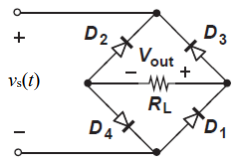
While constructing a Bridge rectifier, the designer mistakenly has swapped the terminals of D3 as shown in the figure below, where • Diode D3 is damaged so that it is always open circuit regardless of the applied voltage. • vs(t) is a sinusoidal signal with a peak value (Vs = 5 V). • Diodes are modelled using the constant voltage model with VDO = 0.7 V • The ac line voltage has an rms value of 120 V and a frequency (f) = 60 Hz • The resistance RL = 10 kohm. a) Calculate the transformer turns ratio (N1/N2) if vs(t) is obtained from the secondary side of the transformer whose primary side is connected to the ac line voltage (which has a 120 V rms value). b) Plot in the same graph the input signal vs(t) and the output signal vout(t) (show all details including amplitudes, time instances, etc.) Please plot the graph. c) Calculate the rms values of the output signal vout(t). (hint: sin2 (x) = 0.5(1- cos(2x)))


While constructing a Bridge rectifier, the designer mistakenly has swapped the terminals of D3 as shown in the figure below, where
• Diode D3 is damaged so that it is always open circuit regardless of the applied voltage.
• vs(t) is a sinusoidal signal with a peak value (Vs = 5 V).
• Diodes are modelled using the constant voltage model with VDO = 0.7 V
• The ac line voltage has an rms value of 120 V and a frequency (f) = 60 Hz
• The resistance RL = 10 kohm.
a) Calculate the transformer turns ratio (N1/N2) if vs(t) is obtained from the secondary side of the transformer whose primary side is connected to the ac line voltage (which has a 120 V rms value).
b) Plot in the same graph the input signal vs(t) and the output signal vout(t) (show all details including amplitudes, time instances, etc.) Please plot the graph.
c) Calculate the rms values of the output signal vout(t). (hint: sin2 (x) = 0.5(1- cos(2x)))
d) If a capacitor C = 3.58 µF is connected across R = 10 kohm, repeat (b) in a new graph
e) With the capacitor C = 3.58 µF is connected across R = 10 kohm, determine the peak-to-peak ripple voltage (Vr) and the conduction angle (ωΔt).

Step by step
Solved in 5 steps with 4 images


