With an aid of timing diagram, show your work on how you determine the sequence of counter in Figure Q1. The counter should begin with the counter cleared. HIGH TO QO T1 Q1 T2 Q2
With an aid of timing diagram, show your work on how you determine the sequence of counter in Figure Q1. The counter should begin with the counter cleared. HIGH TO QO T1 Q1 T2 Q2

Chapter4: Processor Technology And Architecture
Section: Chapter Questions
Problem 4VE

Related questions

Question
Need answer quickly
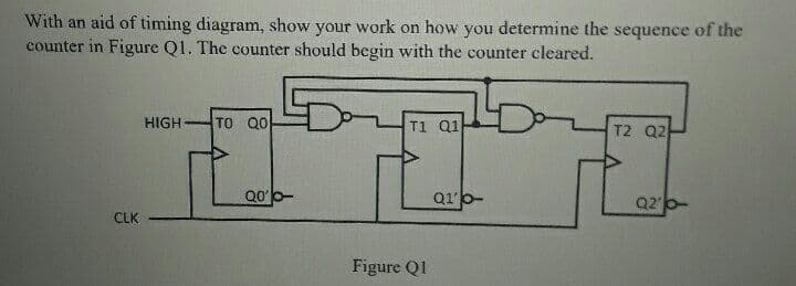
Transcribed Image Text:With an aid of timing diagram, show your work on how you determine the sequence of the
counter in Figure Q1. The counter should begin with the counter cleared.
HIGH
TO Q0
T1 Q1
T2 Q2
Q1p-
Q20-
CLK
Figure Q1
Expert Solution
This question has been solved!
Explore an expertly crafted, step-by-step solution for a thorough understanding of key concepts.

This is a popular solution!

Trending now
This is a popular solution!

Step by step
Solved in 3 steps with 1 images

Knowledge Booster


Learn more about
Need a deep-dive on the concept behind this application? Look no further. Learn more about this topic, computer-science and related others by exploring similar questions and additional content below.Recommended textbooks for you
Systems Architecture
Computer Science
ISBN:
9781305080195
Author:
Stephen D. Burd
Publisher:
Cengage Learning
Systems Architecture
Computer Science
ISBN:
9781305080195
Author:
Stephen D. Burd
Publisher:
Cengage Learning