ww 20 KL0⁰ 
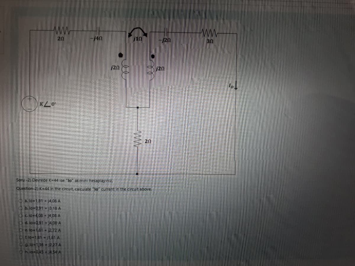
a. lo=1,81 + j4,08 A b. lo=0,91 +13,18 A -j40 Ⓒc. lo=4,08 +14,08 A d. lo=0,91 + j4,08 A De to=1,81 + 12,72 A Oflo=1,81 +1,81 A g. lo=1,36 +12,27 A h. lo=0,45 +4.54 A 120 jin Soru-2) Devrede K-44 ise "lo" akimini hesaplayınız. Question-2) K-44 in the circuit, calculate "lo" current in the circuit above. 20 120 20 www. 30
Q: HHH G G In Fig. capacitance of each capacitor is 11 uF. If the potential difference between the…
A: Given dataCapacitance value,The potential across the capacitance , To find outPotential difference…
Q: 17824 bits of data is to be transferred from a station A to station B. Assume a call setup time of…
A: Given Information:Data size: 17824 bits Call setup time: 0.01 seconds Number of hops: 3 Distance per…
Q: 2- The output of the non-inverting a. Is in phase with the input. amplifier b. Increases with the…
A: “Since you posted multiple questions, we will provide the solution only to the first question per…
Q: 1. The purpose of the Lag Compensator is: I. Improve the study state response of the close…
A: Select the correct option:1. The purpose of the Lag Compensator is:I. Improve the study state…
Q: Find the elements of the equivalent circuit relative to the secondary of a single-phase transformer.…
A:
Q: Q4) If we have a point charge for which Q=4* 10-¹6 and m= 10* 10-26 kg is moving in combined fields…
A: Given Point charge: A point charge is defined as an electric charge assumed to be concentrated at a…
Q: For the following circuit, find the real and reactive power absorbed/delivered by each element 50…
A: The circuit diagram,
Q: Soru 4) Yukandaki devrede R1=59, R2=5 ohm, C1=0.1F, C2=0.2F olduğuna göre transfer fonksiyonu H(s) =…
A: The transfer function of the given circuit across the circuit element needs to be obtained.
Q: 20 www x/_0° A 20 -120 7 YZ0° V Soru 1) Devrede X=7 ve Y=30 ise maksimum ortalama güç transferi için…
A:
Q: Vi www C₁ ww 14+ O a. H(s) = 10s/ (80s^2 + 490,00 + 10) O b. H(s) = 10s/ (80s^2 + 250,00 + 5) O c.…
A:
Q: 2- In the circuit shown below, the capacitor is initially uncharged. Both of the switches are in…
A:
Q: Derive an expression for the x(t) and Determine the Fourier transform of the signal x(t) shown in…
A: Given signal x(t) isWe need to determine the expression of x(t) and Fourier Transform of x(t) i.e X(
Q: Q1) for the signal that is shown in the figure below A) plot the amplitude spectrum X(t) 2 A 4- B)…
A:
Q: In a certain region where the relative permittivity is 2.4, D = 2ax - 4ay+5a-nc/m². Find:…
A:
Q: A 470- uF capacitor is connected in series with a 120- k2 resistor. How long will it take the…
A:
Q: The Bailey unequal-split power divider uses a 90° hybrid coupler and a T-junction, as shown below.…
A:
Q: Task 4 Explain the operation of the NOT gate shown below. This would also involve the regions of…
A: The BHT is three terminal electronic device. It work in three region active, saturation and cut…
Q: a. Determine the value of N2, rounded to the nearest whole number, such that the 16-ohm resistor…
A: here we need to find the let us denote
Q: At the instant the switch is closed in the circuit in (Figure 1), the capacitor is charged to 6.7 V,…
A: Solution:Given Data:=>V=4v=>C= 500nf=>t= 46ms=>V(o)R(0)=5.1Kilo - ohm=>Amplifier =…
Q: 4-0: Determine initial and final values of h(t) = £¹ [H(s)] if 5s² + 5s + 14 s3 +8s² + 12s H(s) =
A: Function is given as,
Q: 2. 1. Use D-type flip-flops and gates to design a counter, repeating binary sequence: 0, 7, 5, 3,
A: Using D flip flop, we have to design a counter that repeats binary sequence: 0, 7, 5, 3, 1.
Q: *5.29 For the circuit in Fig. P5.29, determine the voltages across C₁ and C₂ and the currents…
A: Under dc condition the capacitor behaves as an open circuit and the inductor behaves as a short…
Q: in the circuit shown below, the switch s is closed to charge the capacitor. At an instant during the…
A: voltage across capacitor = Charge/capacitance.Using above calculate voltage across the capacitor.Now…
Q: Memory interfaced to 8086 Microprocessor 16 data bus should be arranged in------ a.One bank. b. Two…
A: “Since you have posted multiple questions, we will provide the solution only to the first question…
Q: Find the amount of energy required to move a 6-C charge from the origin to P(3, 1, -1) in the field…
A: It is given that:
Q: 8- Find E at the origin if the following charge distributions are present in free space: point…
A: X= constant means YZ Plane and X is perpendicular axisY= constant means XZ plane and Y is…
Q: G1 G2 T₁ 1 T₂ Line GI Load 3E Consider the power system given above. Draw the impedance diagram and…
A: The above question is based on the per-unit impedance diagram in Power System.The MVA base is for G1…
Q: 7- The region in which 4 < r < 5,0 <0 < 25°, and 0.9x < < 1.17 contains the volume charge density of…
A:
Q: Given the circuit in Figure below. R1=7, R2=5 ohm, C1=0.1F, C2=0.2F determine the transfer function…
A: For the given circuit the transfer function of across the given element needs to be obtained.
Q: We have two voltages, V1 = 20 volts at an angle of 0 degrees and V2 = 50 volts at an angle of 45…
A: The above question is based on Thevenin's theorem and the transformation of voltages and impedances…
Q: Consider the ac circuit in Fig. 25 cos(4x 10³) V Determine io using nodal method. 2 k Figure 2 µF…
A: it is asked to find the current io using nodal analysis
Q: 1. For the following circuit, a. find a. b. find wo. c. write a differential equation in v(t). d.…
A:
Q: Vi R₁ ww G₁= R₂ ww + C₂ Vo Soru 4) Yukarıdaki devrede R1-87, R2=5 ohm, C1=0.1F C2=0.2F olduğuna göre…
A: The circuit is
Q: A requirement exists for an FIR digital filter to meet the following specifications: Passband edge…
A: Given: A FIR digital filter has the following specification:To find:a) Sketch the tolerance scheme…
Q: (1) a. Current voltage characteristic of a diode i = {kv², v>0 v<0 given in the form. What is the…
A:
Q: Potential Field of a Point Charge Exercise: A 15 nC point charge is at the origin in free space.…
A: The charge, The point,
Q: For the single node pair circuit below is = -0.5 A, R₁ = 10 ohm, R₂ = 115 ohm, R3 = 57 ohm, and R4 =…
A: Given circuit is single node pair circuit,Iₛ= -0.5 AR₁= 10 ohmR₂= 115 ohmR₃= 57 ohmR₄= 124 ohmFind…
Q: VIN R₁ + R₂ OVOUT
A:
Q: A DC circuit which includes Emfx of unkown magnitude and orientation, at the location indicated is…
A: Given Data:Consider the circuit with the given circuit description as,To Find:I. The potential…
Q: x(t) = 1 t≥0 0 elsewhere
A:
Q: Two resistances, one of 35 ohms and another of unknown value are connected in parallel, the total…
A:
Q: R(S) + G₁ + G₂ H₁ I G3 I H3 I H₂ 2 G4
A: Given Data:A block diagram of a system with,Input Output To Find:The transfer function
Q: a) The voltage VF applied to the field circuit b) The internal voltage EA c) The machine speed in…
A: The above question is based on a separately excited DC motor.Since multiple subparts to the same…
Q: When clearing an EPROM for the first time, how should it be done?
A: The question is asking for guidance on how to clear an EPROM (Erasable Programmable Read-Only…
Q: 10) The "Four Quadrant Operation" principle: a) implies that the power is bidirectional. b)…
A: The above questions are based on Power Electronics.
Q: Find the steady-state expressions for the currents i, and it in the circuit in (Figure 1) when v, =…
A:
Q: 4. Exercises Qu 1. Generate Bode Plots of the transfer functions given below. Use them to obtain the…
A: The given transfer functions are as follows,“Since you have posted a question with multiple…
Q: 1. Find the continuous time Fourier series coefficients of the following continuous time periodic…
A: Given:A continuous time periodic signal, To find:Fourier series coefficients of the given signal and…
Q: 1-e (1-² (1-1) ¹) y[m] -[n-41] + #y[nx[n] + x[n-1] dx(t) de + x(t)
A:
Q: Construct a MOD-20 counter using two 74LS90 integrated circuit chips.
A: A MOD-20 counter is a digital circuit that counts in the range of 0 to 19 and repeats. It can be…
Step by step
Solved in 3 steps with 2 images
- A 3 phase 50 Hz alternator is connected to the bus bars through an oil circuitbreaker. Due to short circuit occurring at bus bars, the circuit breaker opens when the r.m.s value of the current was 8000 amperes. The reactance of each phase of the alternator is 2.5 mH and the capacitance to earth between the circuit breaker and the alternator is 1.4 x 10^-7 uF. Determine: (i) Frequency of oscillations(ii) The maximum value of RRRV(iii) Time taken to achieve RRRV value in (ii)A 50 cycles, 3 phase alternator with grounded neutral has inductance of 1.6 mH per phase and is connected to busbar through a circuit breaker. The capacitance to earth between the alternator and circuit breaker is 0.003 uF per phase. The circuit breaker opens when rms value of current is 7500 A. Determine the following: i) Maximum rate of rise of restriking voltage. 1) Time for maximum rate of rise of restriking voltage. in) Frequency of oscillationsIn the given circuit, the amplitude of the input voltage is 13 volts and its phase is 0 degrees.The values of the circuit elements are given below.What is the maximum average power that can be transferred to the ZL load?R = 3 ohmL = 5j ohmC = -6j ohm
- Thus, in the verden circuit IG = 2.00uA is an 8.00kHz sine sign with a peak-to-peak value, L1 = 3.00uA Rs=3.34Kohm, R1 5.12Kohm. R2=3548.67Kohm, R3 =8.73Kohm, R4 =2.16Kohm R5 =23.17Kohm, VCC =11.00V, VEE--10.00V, Vp =6.00V, IDSS = 8.13mA, calculate the voltage value of V0 at the moment of 3T/4 (T=Period).The phase angle between the phase voltage and the line voltage of a Y-connected generator isa. 0°b. 30°c. 60°d. 90°Also fınd the radıal frequency when the current ı0 has a phase of 45 wıth respect to Vs
- A 13.2 kV, 60 Hz, 3-phase synchronous generator is connected in star and its neutral point is earthed while inductance per phase is 0.02 Henry. The generator is connected to a bus bar through a circuit breaker. The distributed capacitance up to circuit breaker between phase and neutral is 0.015 micro Farad. Determine the following: (i) Peak re-striking voltage (in kV) across the contact of circuit breaker; (ii) Frequency of oscillations (in kHz); (iii) Time to occurs first peak re-striking voltage (in micro second) and (iv) The average rate of rise of re-striking voltage (in mega volts per second)If the maximum value of an alternating voltage with a frequency of 35 Hz is 100 V, write the equation for this voltage. A u= 70,7.Sin2,198t B u= 63,6.Sin35t C u= 63,6.Sin35t D u= 100.Sin219,8t E u= 63,6.Sin35tA voltage and current applied to a single phase load is v= 26 cos (300t+25°) and i= 12 cos (250t- 20°). Find the single and three phase active and reactive power of the circuit if the voltage and current are in sine waveform. Three Phase Active power Three phase Reactive Power
- A voltage and current applied to a single phase load is v= 26 cos (300t+35) and i= 19 cos (250t- 20). Find the single and three phase active and reactive power of the circuit if the voltage and current are in sine waveformFind the sum of the voltages and its phase angle and the angle difference of e1=12 sin 10 t + 60oV and e2=6 sin 10 t + 30oV Answer: et= 17.46∠50.10o θpd=30oWhat is the in phase component of 3*rect(t/10)*cos(300*pi*t + pi/2)?