Z1 Zs Z2 Z3
Q: (a) From Figure 2(a), how many branches and nodes does the circuit? Redraw the circuit and label the…
A:
Q: 13. Using series/parallel resistance combination, find the equivalent resistance seen by the source…
A: as per our guidelines we are supposed to answer?️ only one question. Kindly repost other questions…
Q: finite impulse response (FIR) filter has the following transfer function
A:
Q: Determine the total resistance using delta wye transformation.
A:
Q: 8.72 Using loop analysis, find I, in the network in Fig. P8.72. 12/6'v 2/0 A jin
A:
Q: Design a sequential circuit whase state tables are specified in Table shown below, using D-glip.…
A: Here is the solution below for above Mealy machine.
Q: An input x(t) as in Figure Q1(a) is passed through an LTI system with impulse response given by h(t)…
A: The LTI system is very useful representation of output response of any system with a input signal.…
Q: (a) The BJT and FET are the types of transistor that were used as switches and amplifier in…
A: We are authorized to answer one question at a time, since you have not mentioned which question you…
Q: I need conclusion for logic gates
A: Given: Logic gates
Q: Calculate the value of the voltage U2 in the circuit, given: U = 24 V R1 = 3.9 ko R2 = 6.8 kQ R3 : =…
A: Given, U=24 VR1=3.9 ΩR2=6.8 ΩR3=6.8 Ω
Q: 4.a) Realize the given system in direct form-I y[n] = 0.5y[n-1] – 0.25y[n-2] +x[n]+ 0.4 x[n-1]
A: As per our guidelines we are supposed to be answer the first question only. Kindly repost the other…
Q: 1. The bandwidth of the Single-Stage IF amplifier of a Superheterodyne receiver is to be determined.…
A: Input signal Pi=25 dBμ RF amplifier gain PGRF=30 dB Mixer loss PGM=−10 dB IF Amplifer PGIF=20 dB…
Q: 5) One approach to "offset correction" involves the adjustment of the values of Rc1 and Rc2 so as to…
A: The circuit diagram is shown below,
Q: A PMMC instrument gives 27 mA at full scale reading when a potential difference across its terminals…
A: Given: For PMMC Im=27 mAVm=38 mV So, meter resistance Rm=VmIm=38 mV27 mA=1.407 Ω
Q: 5. Assuming an ideal diode, sketch V, V. and ig for the half-wave rectifier below. The input is…
A:
Q: 5Ω 1Ω 2Ω 10 V 4Ω Figure Q2(a)
A:
Q: 1. From the Low pass filter formula, Find Rur: 2. From the High pass mula, Find Rur: 3. Caiculate…
A: It is given that: FL=300 HzFH=900 HzCLP=CHP=0.2μF
Q: nd inverse-time circuitbreaker rating for a circui
A: Circuit breaker When there is fault then the switching device for interrupting the abnormal current…
Q: .150KVA, 440 V, 50 Hz, star-connected diesel generator has armature reaction 1.6 S2 when it is…
A: Star Connection: A way of connecting polyphase circuits in which one end of each phase line is…
Q: 3- Show to connect two 7482 adders to form a four-bit adder? 4- Draw a block diagram for 8-bit…
A: The 4 bit adder can be designed by using the two 2-bit adder and similarly the 8-bit adder can be…
Q: 2. For the cireuit shown in figure below, Current l 6A, I=SA, I=7A. Find the eurrent Is. Ib, la…
A: Given circuit, Where, I1=6 AI3=5 AI5=7 AI6=5 AI9=1 A
Q: Which laws were used by Kirchoff to describe the flow of electrons in a circuit
A: There are two law of Kirchhoff's, Kirchhoff's Voltage Law Kirchhoff's Current Law
Q: 1. Determine Vo I, for the networks below.
A:
Q: The zero-state scaled network shown in Figure 131 is driven by the sinusoidal voltage source Eg(t)…
A: The required current values can be calculated by using the kirchhoff's voltage law to form equations…
Q: Derive the truth table, simplified equation, and logical diagram 1. Design a 4-bit majority…
A: As per our guideline we are suppposed to be answer the first question only. Kindly repost the other…
Q: Transform the given cylindrical vectors into its rectangular form: (a) 5ap, at point F( 1, 2, 3 )…
A:
Q: There are three logic gates. Logic gate A draws 3.6μA when the output is HIGH and 2μA when the…
A: Given: There are three logic gates. Logic gate A draws 3.6 μA when the output is HIGH and 2 μA when…
Q: 11. A standard TTL gate has a fan-out of 10 unit loads. Are any of the gates in Figure 15-51 over-…
A: The number of fan-out is depend on the number of connections made from the output of the gate to the…
Q: If the transducer input is 100 X 10-3 psi and the output is 200 milli-amp. The sensitivity is…
A: Given: Transducer input = 100×10-3 psi Transducer output = 200 mA
Q: choose the correct expression for A +A B C D A + B C В + А С O B+AC OC+A B
A: Given: Boolean expression, F=A+A.B.C
Q: 1) Half wave bridge inverter have following construction find the output signal sequencly depending…
A: Half bridge inverter Vs=60 V Assumptions: 1. Type of load are not specified. We assume resistive…
Q: 3. Design Components 4. The transformation of this filter characteristic can be easily implemented…
A: The band stop filter can be designed with the help of summer. The band stop filter is combination of…
Q: The RL network in Figure 1.170 has been at rest for a long period of time with the switch Si open.…
A: A RL circuit is given in the question. The switch S1 in the circuit was opened for a long period of…
Q: 13.6 The initial charge on the capacitor in the circuit (b) Iab = [20(s + 2.4)]/[s(s + 3)(s + 6)].…
A:
Q: 1) The PWM is new thechnigue adopted in power electronics application .explaine the advantages of…
A: Since you have asked multiple questions, we will solve the first question for you. If you want any…
Q: What is the difference between outsourcing and offshoring and why would a company choose to…
A: Outsourcing and offshoring : Outsourcing refers to an business enterprise contracting education…
Q: Course Name & Code: Signals & Systems (CNET-221) 2. Formally prove whether or not each system is…
A: We need to check whether the system are linear or not .
Q: time constant of an RC circuit,
A: For KVL equations- Summation of voltage drops in a closed loop is always zero. For KCL equations-…
Q: 03/ Simplify the block diagram shown in Fig.(2).determining the overall transfer fumetion. G4 X(S)…
A:
Q: For the system shown by a single-line diagram (Fig. Q2), calculate the three-phase fault level (in…
A: Given:
Q: 21 For the network given. Determine Av. Show solution in your bond paper 12 V 2.2 kN 220 kN B = 60…
A:
Q: A solid conducting cylinder of radius R1 = 10 cm is fixed coaxially within a cylindrical shell of…
A: The uniform charge distribution in a cylindrical coaxial conductor system can be represented by…
Q: In the circuit shown, determine the voltage across resistor R1. R2 2K D1 R1 9V 2K 1.5V
A: In this question, We need to determine the voltage across the R1 resistance using the second…
Q: 8.66 Use nodal analysis to find V, in the circuit in Fig. P8.66. 12,6 v 2V -j1 av, Vo Figure P8.66
A:
Q: 5.22 Consider a feedback system with a plant model (8 – 1)(s – 3) (8 – 2)(s+ 1)²' Use the root-locus…
A: Stable controller: It is a controller that has poles and zeroes on the left half side of the…
Q: The value of zero sequence reactance and positive sequence reactance
A:
Q: 2. Design a clamper to perform the function indicated below. Silicon diodes 10 V -10 V -173 V
A: Please refer the attached images for the complete answer..
Q: Explain the operation of an ideal diode
A: In this question we will explain operation of an ideal diode....
Q: A JFET data sheet specifies VGS(off) = –10 V and IDSS = 8 mA. Find the value of ID when VGS =
A: It is given that: VGSoff=-10 VIDSS=8 mA=8×10⁻³ AVGS=-3 V
Q: Determine the output waveform for the network of figure below and calculate the output dc level.
A: Given: Let Vs=supply voltageVo=output voltagef=60 HzVoltage drop across diode=0.7V( Si…
determine the (a) total real power, (b)the total reactive power, (c) the complex power and (d) the overall power factor
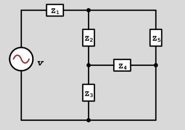
Trending now
This is a popular solution!
Step by step
Solved in 4 steps with 4 images
- A HV transmission line having receiving end load is 300MVA, 50 Hz line from poin A to point B. Resistance 0.13 ohm/KM , for 160 KM Inductance XL= 0.4 ohm per kilometer Parallel admittance j318 × 10-6 Power Factor 0.8770, 0.8477 lagging, unity and 0.8770, 0.8477 leading Assume desired voltage at the receiving end of the transmission line is not less than 380kV., if the line is supplying rated voltage and apparent power at various power factors given Estimate : a. Sending end voltages b. Voltage regulation c. Efficiency of the transmission line d. Give a technical explanations on the results obtainedIn the circuit below, find the value of the load impedance ZL, which must be connected to the output of the circuit for MAXIMUM POWER TRANSFER. If this load impedance you found is connected, what is the amplitude, phase angle and angular frequency values of the circuit that will pass through the circuit? AB=34, BA=43A single phase, 50Hz transmission line connected between two buses having line resistance of 3Ω, inductive reactance of 0.2 Henry. Both the ends of transmission lines are connected with series capacitors of 400microfarads each for series compensation. Then series impedance of the line is a.(3-j31) Ω b.(3-j59.6) Ω c.(3+j31)Ω d.(3+j59.6) Ω 2- Fast decoupled algorithm is not as accurate as the exact Newton Raphson algorithm for Variable number of iteration Fixed number of iteration Variable time per iteration Fixed time per iteration
- A ower system is operating at 1000Mw, 132kV, 50Hz, with 0.8 p.f. laging in parallelwith another line at 750OMW, 132kV, 50Hz with 0.707 p.f. lagging. Both are interconnectedat the station and when the compensating device is on, the overall power factor isimproved to 0.9 lagging. Suggest suitable capacitors, shunt and series. Individual loadsand combined load are to improve power factor to 0.9 in all cases.A series circuit of RLC with following parameters, R=15 ohm, L=20 m H & C=100 micro Farad. VT=169.7 sin (337t-30) Volt. Find the following: Zt, , It, Voltage across each element, Power factor, apparent power, real or average power and reactive power and the total phasor diagram and power phasor diagramA transmission line has generalized circuit constants are A=0.93+j0.016,B=20+j140.The load at the receiving end is 60MVA, 50HZ, 0.8 power factor lagging. The voltage at the supply end is 132KV. Caluclate the load voltage and voltage regulation,Use nominal-π approximation.
- Q5. A single phase overhead transmission line has a supply voltage of 34 kV and a sending end current of magnitude 40 A at 0-8 p.f. lagging is feeding a certain load. The total resistance and inductance of the line are 5 and 21 mH respectively. Draw the practical circuit used and the devices necessary to perform this experiment. Then calculate the sending end power, receiving end current, voltage, power factor, receiving end power and line efficiency Vs 34000 Is 40 Cosos 0.8 R 5 Ps Ir Vr Cosor Pr n 21e-3S.2) The serial impedance of the 300 km power transmission line is 23 + j75 ohm / phase and the shunt acceptance is j500 microS / phase. A power of 50 MW with a power factor of 0.88 under 220 kV interphase voltage from the end of the power transmission line being shot. Using these data of the energy transmission line, a) Characteristic impedance of the energy transmission line, b) Natural apparent power of the energy transmission line according to the 220 kV interphase operating voltage, c) The values of the line parameters A, B, C and D of the transmission line using hyperbolic functions, d) Calculate the maximum power that the power transmission line can transmit.S.4) the length of a three-phase power transmission line with a Nominal operating voltage of 69 kV is 16km. The impedance of the transmission line per unit length is 0.125 + j0.4375 ohm/km. From the end of the line, a 56 MW star connected load is fed with a power coefficient of 0.8 back under a 64 kV interphase voltage. If the line head voltage of the transmission line is 69 kV, calculate the capacity and power of the star-connected capacitor to be shunted into the load connected to the end of the line.
- 4 Sinusoidal voltage source of us(t) = [100 cos ωt]V , (ω = 20Mrad s ) voltage is connected to the input of a transmission line of h = 10m length. The wawe parameters of the line and the impedance of the loading two-pole connected to the output at ω angular frequency are: Z0 = (49, 5 - j2)Ω, γ = (0, 5 + j40)km-1, and Z2 = Z0. Find the voltage amplitude at the nearest point to the source where the voltage phase angle is 0! a) U = 100V b) U = 92, 4V c) U = 36, 8V d) U = 50VTransmission line with a load Zl = 100 + i80 ohm with characteristic impedance of Z0 = 5 ohm is designed. The transmission line operates at 100 MHz, where is matched with a shunt single- stub tuner. a)Calculate the stub positions. b)Calculate the stub length where open circuit stub is used. c) Calculate the stub length where short circuit stub is used.A 3 phase 170KV, 50 HZ transmission system is 170km long. The resistance is 0.5Ω/km/phase, inductance of 1mH/km/phase and capacitance of 2nano farad/km/phase. The line delivers 60MW and 93MVAR at 170KV line to line voltage. Using suitable mode determine sending and receiving end currents. What can you infer from the result?