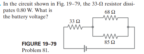
. In the circuit shown in Fig. 19–79, the 33-N resistor dissi- pates 0.80 W. What is the battery voltage? 68 Ω 33 Ω FIGURE 19–79 85 2 Problem 81.
Q: A flashlight bulb rated at 2.0 W and 3.0 V is operated by a 9.0-V battery. To light the bulb at its…
A: The current across the bulb can be obtained as P=VbulbII=PVbulb=2.0 W3.0 V=0.67A
Q: Find io(t) in the circuit of Fig.8 when i,(t) = 10 sin 2t A. i,(1) 0.5 F Fig.8 2. ww
A:
Q: 5 For each circuit in Fig. 27-20, are the resistors connected in se- ries, in parallel, or neither?…
A:
Q: 8.5 At 1= 0.15 s in the circuit of Fig. 8.21, find the value of (a) i: (b) i; (c) i2. Ans: 0.756 A;…
A:
Q: Consider the circuit shown below. (Assume & = 9.00 V, R, = 1.90 N, R, = 4.10 N, R3 = 6.40 n, and R,…
A:
Q: 13-15. For the circuit below, i, = 1.4 A. Calculate ix and the total power dissipated by the…
A: io = 1.4 ALet, Ro = 16 Ω, R1 = 8 Ω, R2 = 4 Ω, and R3 = 2 Ω
Q: Problem 28.17: Consider the combination of resistors shown in Figure below. If a voltage 35V is…
A: Please see the answer below.
Q: Which resistors in Fig. 19–41 are connected in parallel? (a) All three. (b) Rị and R2. (c) R2 and…
A: Circuit is given
Q: "If the voltage is increased, then the electrical energy will be (keeping Resistance and time…
A: Given:
Q: 102 50 Fig. 20-52 II Draw a circuit diagram of the circuit in Fig. 20-53. 10 2
A:
Q: For the circuit shown in Fig. 19–80, determine (a) the current through the 16-V battery and (b) the…
A:
Q: If Req = 50 2 in the circuit in Fig. 2.101, find R. 10Ω 30 Ω ww Rea 12 Q 12 Q 12Ω 60 2 ww ww ww ww
A:
Q: When the switch shown in Fig. 19–45 is closed, what willhappen to the voltage across resistor R1 It…
A: When switch is closed, R2 connect parallel in the circuit. Hence, equivalent resistance of the…
Q: 3) Caleulate the unknown resistance (r) in the circuit shown in Figure-4(C), if the equivalent…
A: solution of above circuit given in below step with proper explaination.
Q: (II) In Fig. 19–69 (same as Fig. 19–20a), the total resistance is 15.0 kN, and the battery's emf is…
A: Given: The total resistance of the circuit is R=15 kΩ. The emf of the batter is Vmax=24 V. The time…
Q: Find ve(t) in the circuit of Fig.7 if v,(t) = 2e-3tu(t).
A:
Q: (I) Calculate the current in the circuit of Fig. 19–53, and show that the sum of all the r= 2.0 2…
A:
Q: 18- chapter28-question19 Calculate the power (in W) dellvered to 4 0 resistor in the circuit shown…
A:
Q: (II) Electrocardiographs are often connected as shown in Fig. 19–68. The lead wires to the legs are…
A: Given: The time constant is 3.0 s. The capacitance is 3.0 μF.
Q: 1. In which circuits shown in Fig. 19–40 are resistors connected in series? (a) (b) w ww (c) (d)…
A: The resistances are treated as connected in series when the same current flows through the…
Q: Design a circuit in which two different switches of the type shown in Fig. 19–39 can be used to…
A: Consider the circuit diagram with two switches for different rooms operating the same bulb.
Q: Determine the equivalent resistance of the circuit shown, the voltage across each resistor, and the…
A: Given: Three resistance 750Ω, 680Ω, and 990Ω are connected with 12.0 V battery as shown in the…
Q: 16. (II) Determine (a) the equivalent resistance of the circuit shown in Fig. 19-48, (b) the voltage…
A: (a) Since two resistors (750 and 680) are connected in parallel so equivalent resistance will be…
Q: 24. (III) Consider the network of resistors shown in Fig. 19-52. Answer qualitatively: (a) What…
A:
Q: -37 In Fig. 27-48, the resistances are R, = 2.00 N, R, = 5.00 N, and the battery is ideal. What…
A: Given,
Q: ww 10.5 A mum 10 0 10 V In the circuit shown above, the value of r for which the current I is 0.5…
A: This question is based on the combination of resistances. Option b 20 ohms is correct answer.
Q: 9-10. Three resistors of 2.0 , 3.0 2, and 4.0 0 are connected in (a) series and (b) parallel. Find…
A:
Q: 17-2.A given copper wire has a resistance of 5.18 Ω at 20.0°C while a tungsten wire of the same…
A: Given, resistance of copper wire at 20.0°C , Rcu = 5.18 Ω resistance of tungsten wire at…
Q: Consider a circuit with three resistors, R1 = 225 Ω, R2 = 155 Ω, and R3 = 135 Ω, connected in…
A: Given: Three resistors, R1 = 225 Ω R2 = 155 Ω R3= 135 Ω, connected in parallel with a 24.0-V…
Q: Find the Thévenin equivalent of the circuit shown in Fig. 5-18. 10 N 30 V 40 40 N V 100 V을 20 A 90…
A:
Q: 7. When the switch shown in Fig. 19–45 is closed, what will happen to the voltage across resistor…
A: When the switch is open, the current does not flow through the resistor R2. The current flows only…
Q: - (II) A bird stands on a dc electric transmission line carrying 4100 A (Fig. 18–34). The line has…
A: Current, I = 4100 A Resistance, R = 2.5 x 10⁻⁵ ohm
Q: (I) Calculate the current in the circuit of Fig. 19-53, and show that the sum of all the voltage…
A: We have a circuit with a battery of voltage V=9 V and internal resistance r=2 ohm and two resistors…
Q: 11- 3. Several resistors are connected to two batteries as shown in Figure. According to Kirchhoff's…
A: To obtain these type equations from a circuit we use Kirchhoff's voltage law. Which states, net…
Q: culate the magnitude and direction of the currents resistor of Fig. 19–58. 5.8 V 25 2 3.0 V 120 2 56…
A:
Q: Figure 19–44 shows three identical bulbs in a circuit. What happens to the brightness of bulb A if…
A: Redraw the circuit diagram when bulb B is replaced by the short circuit.
Trending now
This is a popular solution!
Step by step
Solved in 3 steps
- The ignition circuit of an automobile is powered by a 12-V battery. How are we able generate large voltages with this power source?Check Your Understanding The voltage supplied to your house varies as V( t )= V max sin( 2ft ) If a resistor is connected across this voltage, will Ohm’s law V = IR still be valid?Refer to Figure 10.17 and the discussion of lights dimming when a heavy appliance comes on. (a) Given the voltage source is 120 V, the wire resistance is 0.800 and the bulb is nominally 75.0 W, what power will the bulb dissipate if a total of 15.0 A passes through the wires when the motor comes on? Assume negligible change in bulb resistance, (b) What power is consumed by the motor?
- When the switch shown in Fig. 19–45 is closed, what willhappen to the voltage across resistor R1 It will(a) increase. (b) decrease. (c) stay the sameSuppose E = 10.0 V, R1 = 180 ohms, and R2 = 350 ohms. See attached. What value of R3 do we select so the battery supplies 24mA? I think first we convert latter, then.... (III) What would the current be in Fig. 19–61 if the 12- Ωresistor is shorted out (resistance= 0 )? Let = 0 r = 1.0 Ω .
- Can a copper wire and an aluminum wire of the samelength have the same resistance? Explainthe battery shown in the circuit in Figure 19.46 has no internal resistance. After you close the switch, the brightness of bulb B1 willA. increase. B. decrease. C. remain the same.(only 1 option is correct)A close inspection of an electric circuit reveals thata 480 ohm resistor was inadvertently soldered in the placewhere a 350 ohm resistor is needed. How can this be fixedwithout removing anything from the existing circuit?
- Just curious as to how they got 292 ohms in the first part of the problem. Thanks.Hi, here's my question. 26.60: In the figure, find the emf e in order for the current through the 7.00 W resistor to be 18.0 A. Each emf source has negligible internal resistance.A person notices a mild shock if the current along apath through the thumb and index finger exceeds 80. µA. Compare the maximum possible voltage without shock acrossthe thumb and index finger with a dry - skin resistance of 4.0 x10⁵ Ω and a wet - skin resistance of 2.0 kΩ.