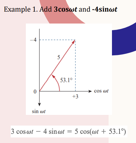
.. Add 3coswt and -4sinwt


Q: 4. Consider the close loop system W(s) = Determine the steady-state error, if input: 4.1 r(t) =…
A: Type of control system Closed-loop control system The more accurate response even in the case on…
Q: Refer to this figure. Find the value of PD. Vio 10 μF 250 ΚΩ ww 20V ww 6.8 ΚΩ B=90 www •1.2 ΚΩ 10 μF…
A:
Q: PART (1) Assume capacitor is fully charged when switch is at position 'a' for about 10 minutes. The…
A: Given- Part (I) The capacitor is fully charged when the switch is at position 'a' for about 10…
Q: Q2:- Draw the circuit of the current series feed back transistor amplifier2) How could you decrease…
A:
Q: 3.16 A three-phase, full-wave half-controlled rectifier bridge circuit is operating at a delay angle…
A: As per the guidelines of Bartleby we supposed to answer first three subpart only for solution of…
Q: aw the digital filter mentioned by H[z)=Y[z]/X[z]. when Y[n]- {2,3*,1, 7)and X[n] {1,-1,2}
A:
Q: Solve the following system
A:
Q: : An inverting amplifier contains a non-ideal Op-Amp with 13V Sk R-80k; R=0; A-600. Let the voltage…
A: We need to write down the nodal equation for given circuit.
Q: nd and sketch the domain of the function f(x, y) :
A:
Q: 2. A two-stage amplifier is designed for radio frequency communications. (a) Identify the…
A: The amplifier circuit is given as The system parameter are given…
Q: 3. True or False O O O It is not a must that = 0 to have an unstable system. (True/False) We can't…
A: We need to tell about whether the given statement are true or false.
Q: M3 Discuss merits, limitations and pitfalls of approaches to data collection and analysis
A: There are several approaches to data collection and analysis in solar panel research and…
Q: = Find v(t) for t> 0 for the given circuit. 12 u(t) 2 0.5 H 3 ww 4 + v (t) I
A:
Q: Show a diagram of how fr4 relates to a roger port?
A: It is asked to show a diagram how fr4 relates to a roger port.
Q: The transfer function of a linear time invariant system is given as 2 Z-¹ (1-0.5 Z-²) The steady…
A: it is asked to find the steady state output value of given discrete transfer function for unit step…
Q: Explain how you would create a pcb design for transmission line?
A: Transmission lines in the printed circuit board layouts are created mainly by using the two…
Q: Exercise 2 Given the function F = A.((B.C). (A + B + C + D)) a) Implement the function F using 4 to…
A:
Q: For the open-loop pole-zero plot in the following figure (with unity feedback): R(s) with G(s)- K…
A: Given data, Open loop transfer function is given as, Gs=ks+1s+2s+3.
Q: (i) By applying Kirchhoff's laws to loops ADCA and BCDB, deduce an expression for the resistance of…
A: Given circuit,
Q: 3-φ induction motor
A:
Q: Two coils having inductance of 0.2H and 2.45H are coupled and their mutual inductance is 0.14H. The…
A: Given- Inductances of coils- L1=0.2 H,L2=2.45 H, Mutual inductance M=0.14 H, To Find- The…
Q: Using compensation theorem Calculate the new values of currents in the network when resistor R3 is…
A:
Q: :) Determine I, R₁, It 30V I vg 452 155 6 201 I, 8n v b 5 11.
A:
Q: 2. A B What particle has an electrical charge -1.6-10-19, Electron Proton C Neutron D Atom Coulomb?
A: Charge The physical characteristic of matter that causes it to feel a force when exposed to an…
Q: 3Ω 6yL0° V 4Ω 6 Ω +yΩ Figure 1 8 Ω 2 Ω 12yL120°
A:
Q: SV M 40V Given the circuit below, find the current /. 1052 IA
A:
Q: Q2:- Draw the circuit of the single stage transistor amplifier2) How could you increase the output…
A:
Q: A conductor 0.2 m long is carrying a current of 20 A at right angles to a magnetic field of 0.5…
A: Given- Length of conductor L=0.2 m, Current I = 20 A, Magnetic field B=0.5 T, Current is increased…
Q: A single-phase semiconverter bridge rectifier operating at a delay angle a and connected to highly…
A:
Q: P2. A closed loop unity feedback system, in fig.P2, oscillates with a frequency of 2 rad/sec. Find…
A:
Q: 21. Calculate a d express the output voltage in terms of magnitude and phase.
A: Given circuit,
Q: (a) Mr. Fareez Ezwan implemented a PID controller to control his aerial drone. The drone produces a…
A: The constant input can be treated as step input. The output is a sinusoidal pattern with no decay…
Q: A 60 Hz, 13.5kV/240V, single-phase ideal transformer is used to step-down the voltage of a…
A: Given: A 60 Hz, 13.5 kV, 2400/240 V, single-phase ideal transformer is given. The low voltage side…
Q: Compute the divergence and curl of the following vectors: a. F = x² ax (z³ − 3x)ay + 4y² az - x³y² Z…
A:
Q: Q1. (True or False): The convolution of x[n] with shift impulses, x[n]*δ[x-5] is x[x+5]?
A:
Q: คำถามท้ายการทดลอง 1. จากวงจรไฟฟ้าต่อไปนี้ กำหนดให้ V1 = V2 = V3 = 5 V และ R1 = R2 = R3 = 20…
A:
Q: The bridge parameters of the circuit shown in Figure Q1 (b) are V = 10V; R1 = 1800; R2 = 170002.…
A: We need to find out the resistance value for balance bridge and galvanometer current and…
Q: The transistor parameters for the circuit in Figure P11.9 are: B = 100, VBE (On) = 0.7 V, and V₁ =…
A: The required parameters can be calculated by using the DC analysis of the differential amplifier…
Q: Question 2 The maximum efficiency (in percentage) at unity power factor for 2500/ 250V, 20KVA,…
A: Given- 2500/250 V, 20 KVA, 1-phase transformer- Core loss=50 W, Ohmic loss at 5/4 loading=100 W, To…
Q: Q/Design a circuit to limit a (20 Vrms) sinusoidal voltage to a maximum positive amplitude of (10 V)…
A: Conceptual background:- Circuits:- A circuit is a fully enclosed circle through which electricity…
Q: Example 2. Find v(t) and i(t) in the circuit shown in Figure 9. v=20 sin(10t+30°) V i Figure 9. Ans:…
A:
Q: Consider a continuous source X that is quantized into an output Y = g(X) with L levels, where g(.)…
A: The entropy of a continuous source X is a measure of the uncertainty or randomness in the source. If…
Q: The power input to the rotor of a 400 V, 50 Hz, 6-pole, 3-phase induction motor is 20 kW. The slip…
A:
Q: Figure 1 shows an n-channel metal-oxide-semiconductor field-effect transistor common-source circuit.…
A: We need to find out the value of source resistance for given current and we need to find out drain…
Q: SV m 40V 1052 IA
A: Given data, Circuit diagram is given as,
Q: Q1: compare with aid of all equations and figures between the frequency division multiplexing (FDM)…
A: Q1) Frequency division multiplexing In FDM the channel is divided into two or more than two…
Q: . The following control system is given (fig1): FF FW C DC P D Fig.1 Where r- is reference y-…
A:
Q: A particle of charge q_1 is located at a distance "a" from us (observer) and a particle of charge…
A: We need to find out the force between given charges .
Q: Block diagram find the transfer function Y(s)/N(s)
A: Block diagram and signal flow graph is pictorial representation. In block diagram system variable…
Prove the answer on this characteristics of sinusoids


Trending now
This is a popular solution!

Step by step
Solved in 3 steps with 3 images


- Clear solutions pls. Thank you Given the following Resistances and Capacitors in Series and Voltage Source: R1 = 1 ohms R2 = 10 ohms C1 = 0.007 Farad C2 = 0.008 Farad Vs = 9 Volts Frequency = 6 Hz What is the Total Reactance in ohms?PLEASE ANSWER LETTERS D & E PLEASE SHOW YOUR DETAILED SOLUTION. WILL GET A LIKE A 25- W resistor and a 300-mH inductor are connected in parallel across a 120-V, 50-Hz source. Determine the magnitude of the following: (a) admittance; (b) current through resistor and inductor; (c) the total current; (d) true power and inductive reactive power; (e) apparent power, power factor, and power factor angle.How do you find Vo and V1 using a delta to wye conversion?
- A) Draw the dc analysis equivalent circuit and ac analysis equivalent circuit. B) Conduct the dc analysis to determine VB, VE, IE, Rin(base), Rin(tot), AV given that βdc = 80 and βac = 100. Please show all calculations steps and thank youTable 9.1 Calculated Measured Is(p-p) 15.05mA∠-57.86° 15mA IL(p-p) 12.732mA∠-90° 12.6mA IR(p-p) 8mA∠0° 8mA VRs(p-p) (for Is) 150mV 150mV VRs(p-p) (for IL) 126mV 126mVThe sinusoidal voltage source in the circuit in (Figure 1) is developing a voltage equal to 50sin400tV. Suppose that R = 480 Ω.Find the Thévenin voltage with respect to the terminals a,b. In rectangle form. Find the Thévenin impedance with respect to the terminals a,b. in rectangle form
- PLEASE SHOW YOUR DETAILED SOLUTION. WILL GET A LIKE A 25- W resistor and a 300-mH inductor are connected in parallel across a 120-V, 50-Hz source. Determine the magnitude of the following: (a) admittance; (b) current through resistor and inductor; (c) the total current; (d) true power and inductive reactive power; (e) apparent power, power factor, and power factor angle.Identify the characteristics of AC and DC voltage. Runs at a higher temperature Answer 1Choose...DCAC More dangerous to transfer Answer 2Choose...DCAC Easy to produce Answer 3Choose...DCAC Easier to transform voltages Answer 4Choose...DCAC Voltage remains at a constant value Answer 5Choose...DCAC Cheaper to producePLEASE SOLVE THE LETTERS D & E. PLEASE SHOW YOUR DETAILED SOLUTION. WILL GET A LIKE A 25- W resistor and a 40-µF capacitor are connected in parallel across a 120-V, 50-Hz source. Determine the magnitude of the following: (a) admittance; (b) current through resistor and capacitor; (c) the total current; (d) true power and capacitive reactive power; (e) apparent power, power factor, and power factor.
- Question : Explain the concepts of lattice matched hetero-structure. Don’t copy other works. Sub:Optoelectronic Dept: EEEA 25- W resistor and a 300-mH inductor are connected in parallel across a 120-V, 50-Hz source. Determine the magnitude of the following: (a) admittance; (b) current through resistor and inductor; (c) the total current; (d) true power and inductive reactive power; (e) apparent power, power factor, and power factor angle.Solution all part