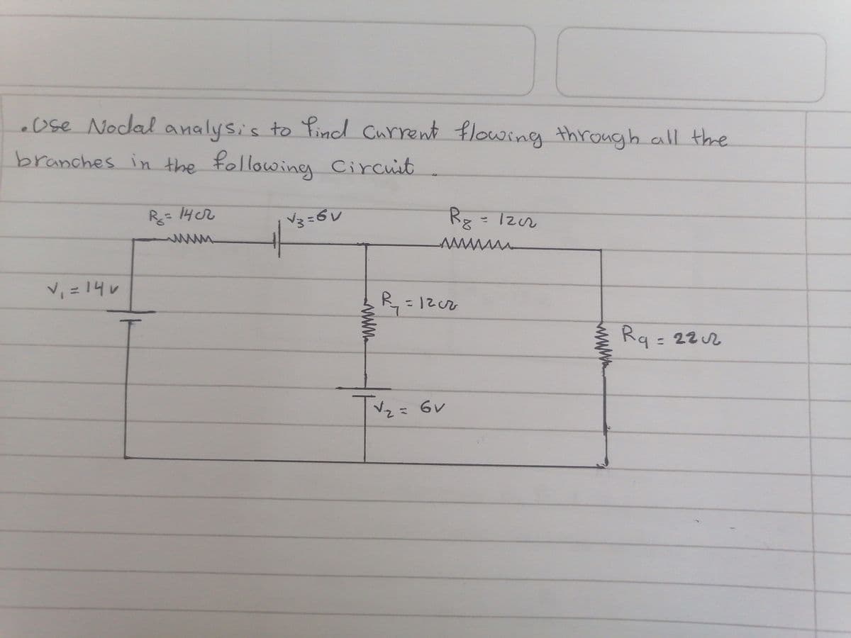
.Use Nodal analysis to find current flowing through all the branches in the following Circuit V₁ = 14v R = 14 cr √3=6V R8 = 1202 www. R₁₂₁ =1202 √√₂ = 6v www. Rq= 22 2


Q: A 250 V, 25 kW dc shunt motor has an efficiency of 85% when running at 1000rpm on full load. The…
A:
Q: Calculate the capacitive reactance if five 40 fF in parallel is connected to a frequency generator…
A:
Q: Briefly explain conduit wiring as applied to domestic or industrial wiring and list two (2)…
A:
Q: Design and implement (draw the circuit) the output f(12) of a 7 segments decoder as a function of…
A: Seven Light Emitting Diodes (LEDs) are placed in a specific pattern (common cathode or common anode…
Q: Find the transfer function G(s) = VL(S)/V(s) for the network using Nodal analysis: v(1) 192 0000 1Η…
A: We need to find out the transfer function for given circuit by using nodal analysis.
Q: A communications link has a transmitter with a power of 8.7 W. The receiver needs a minimum received…
A: Given, Power of the transmitter, PT=8.7 W Power received by the receiver, PR=5.3×10⁻³ W link loss…
Q: 3) For the two circuits shown below calculate the voltage, VAB. Hint: start by calculating the…
A: In this question, We need to determine the voltage across the terminal A and B. We are solving…
Q: 2.A 3-phase motor having a star connected rotor has an induced emf of 150 volts between slip rings…
A: Given that: The 3-phase motor has star connected rotor Induced EMF 150 V at a standstill on an open…
Q: (a) Fill the following table v₁ (t) v₂ (t) Max. value v₁ (t) = 5 + 20 sin(400t +30°) V₂ (t) = 10…
A:
Q: 2 A generation station of 1 MW supplied أعلى قيمة هي رادم فيها واط ۱۰۰۰۰۰ dregion as follow: from…
A:
Q: A charge of 10 Chas velocity of V=2a, +32a,-4a, m/s. Find Fon the charge in the field of E=6a, + 5ā,…
A: Given that, Q=10 C E→=6 ax→+5ay→+9az→ V/m V→= 2 ax→+32ay→-4 az→ m/s Here we have to calculate only…
Q: Opens at t=0 s 100 V 60 Ω Μ 40 Ω . 10Ω 2.0 με :
A: The switch has been closed for a very long time. We need to determine a) What is the charge on the…
Q: Calculate the value of current through each resistor, the total current, and the total resistance…
A:
Q: Find the resistance of an annular wedge of conducting material, assuming the current flow is radial…
A: A form consisting of two circles is essentially what an annulus or the annular area is. It is a…
Q: An open loop control system results in -2t a response of € (sin5t+cos5t) for a unit impulse input.…
A: It is given that: xt=e-2tsin5t+cos5t
Q: C 1. Symptom: The voltmeter 1 reading is 0 V, and the voltmeter 2 reading is 20 V. Cause: (a) R₁ is…
A:
Q: Unity feedback system with G(s) = = K(s+4) s(s+1)(s+2) a) Find range of K that keeps the system…
A: We need to find out range of K for stabe , marginal stable system and frequency of oscillation for…
Q: 10. Use mesh analysis to obtain lo. 492 σου (1) ΤΩ Μ Μ 2Ω Μ 5A 3Ω Μ ( 10 A Το ΖΩ Μ 192 Μ 4Ω (+1 ΤΩ…
A: We need to find out the current for given circuit by using of mesh analysis .
Q: give the transfer function of this block diagram (STEP BY STEP) and error ratio.
A: ecalculation of transfer function of this block diagram and error ratio.
Q: For the circuit shown below, given that v = 5 V: a) Calculate the voltage drop across the 6 A and 9…
A: The given problem is from circuits. The problem can be solved by using KVL.
Q: A short shunt compound DC generator delivers a load current of 30 A at 220 V and has armature,…
A:
Q: 7.10 Use the differential equation approach to find u (1) for 1> 0 in the circuit in Fig. P7.10.
A: It is given that:
Q: Which type of compensation is show by the plots
A: According to the question, for the given graph as shown below We need to find the types of…
Q: Assuming the passive sign convention, sketch the voltage which develops across the terminals of a…
A: It is given that: C=2.5 F
Q: 2. For the circuit shown, find, using the Kirchhoff's Law, (a) the current flowing in and the pd…
A:
Q: What is the transfer function of the system given by differential equation? (ILO2) d²y + 6y + 5y = u…
A:
Q: (a) Using the Quine-McCluskey method find all prime implicants of f(A, B, C, D) =…
A: Given & to find: (a) Using the Quine-McCluskey method find all prime implicants of f (A, B, C,…
Q: 3. Find the DFT of the discrete data x[n] = [1, 2, 3, 1].
A:
Q: Figure 1 shows a single line diagram of a part of the three-phase power system. The ratings of the…
A: Given We have to draw per unit equivalent circuit with base values Vbase,new =13.8 kV MVAbase, new…
Q: A boost converter is operated from a source voltage of 100V with a duty ratio of 0.4. The load…
A: Given- Source or input voltage, Vin=100 V. Duty ratio, D=0.4. Load resistance, RL=400 Ω. Internal…
Q: Calculate the resistance of a #20AWG copper wire that is 50 km long.
A: . SOLUTION GIVEN AREA IN AWG = 20AWG LENGTH (L) = 50 km
Q: Show the complete and step-by-step solution for an upvote. a. The voltage source value if the power…
A: In this question We need to determine the value of source voltage and power delivered by the source…
Q: 4. In a balanced three phase system the line voltage Vab =220cis(30°) volts and line current Ic =…
A: In this question, We need to determine the power of the Delta system. Power P= 3Vph Iph cos(Vph ^…
Q: 2. For the circuit shown, find, using the Kirchhoff's Law, (a) the current flowing in and the pd…
A: As per our company guidelines we are supposed to answer only first three subparts kindly repost the…
Q: help
A:
Q: SO OD R U Q X D D
A:
Q: V 153.3333 Ω Ic Im| 0.0084633 Ω j197,2234Ω j0.0246696 Ω 230<0° V Zı | 2420° Ω
A:
Q: a. x [n] = -5(4) ^u[n]
A: In this question we need to find a roc and z transform of the given signal.
Q: Unsimplified Boolean expression and truth table pls.
A:
Q: Derive an expression for out in terms of us for the amplifier circuit shown in Fig. 7.71. FIGURE…
A:
Q: OD 7. B-J OM On 0 VI) In source-free region VD = PU √. B = 0 for static fields, VxE=0 In non…
A: 3rd 4th 5th 7th are correct
Q: 6. Apply nodal analysis to solve for Vx. 24 Ο 10 Ω ΜΕ +1 άλλ 201 10.2V,
A:
Q: 11.Calculate the unknown voltages, currents, and powers and properly label the schematic. E1 12 V +…
A:
Q: Explain the relationship between Gain-to-receiver system’s noise temperature ratio (dB) and the…
A: The ratio of a receiver's input and output signal power, often represented in decibels. Gain in…
Q: The current through a 17 nH aluminum inductor is shown in Fig. 7.47. Sketch the resulting voltage…
A: Given,
Q: Q- A 20 MVA, 11.2 kV, 4-pole, 50 Hz alternator has an inertia constant of 15 MJ/MVA. If the input…
A: Given- 20 MVA, 11.2 kV, 4-pole, 50 Hz alternator, Machine rating G=20 MVA, Pole P=4, Frequency f=50…
Q: 1. Determine the Fourier transform of the following function a. x(n) = 3" u(n) b. x(n) = -0.55" u(-n…
A: In this question, We need to determine the Fourier transform of the given signals. We know,…
Q: (a) Obtain an expression for vc in the circuit of Fig. 8.87 valid for all values of t. (b) Sketch…
A: In this question, We need to determine the expression of the voltage across the capacitor C as…
Q: + (d) Find an expression for the maximum current in the inductor over one cycle of the external AC…
A: Given that, Vac (t)= V0 Cos(Ωt+ϕ) R, L, C, Ω and ϕ are arbitrary positive constants. Here we have…
Q: QUESTION 9 The output Lot Full Light will be energized when the accumulated count is: Ladder logic…
A: Given:

Step by step
Solved in 2 steps with 1 images


- Answer the following questions related to a series/parallel combinational circuit configured as follows: R1 and R2 are in series with the source and these two resistors (R1 and R2) are in parallel with R3. The circuit’s voltage is +18VDC, R1= 1.5kΩ, R2=4.5KΩ, and R3=30kΩ. The current drawn by R2 in the circuit describe above is _________. Use correct engineering notation and unit measure!Answer the following questions related to a series/parallel combinational circuit configured as follows: R1 and R2 are in series with the source and these two resistors (R1 and R2) are in parallel with R3. The circuit’s voltage is +18VDC, R1= 1.5kΩ, R2=4.5KΩ, and R3=30kΩ. The voltage drop across R1 in the circuit described above is __________. Use correct engineering notation and unit measure!Answer the following questions related to a series/parallel combinational circuit configured as follows: R1 is in series with the source and also in series with the parallel combination of R2 and R3. The circuit’s voltage is +24VDC, R1= 4.5kΩ, R2=30kΩ, and R3=10kΩ. The voltage drop across R1 in the circuit described above is __________. Use correct engineering notation and unit measure!
- Answer the following questions related to a series/parallel combinational circuit configured as follows: R1 and R2 are in series with the source and these two resistors (R1 and R2) are in parallel with R3. The circuit’s voltage is +18VDC, R1= 1.5kΩ, R2=4.5KΩ, and R3=30kΩ. The total resistance of the circuit described above is _________. Use correct engineering notation and unit measure!Answer the following questions related to a series/parallel combinational circuit configured as follows: R1 is in series with the source and also in series with the parallel combination of R2 and R3. The circuit’s voltage is +24VDC, R1= 4.5kΩ, R2=30kΩ, and R3=10kΩ. The current drawn by R3 in the circuit describe above is _________. Use correct engineering notation and unit measure!Answer the following question related to a series/parallel combinational circuit configured as follows: R1 is in series with the source and also in series with the parallel combination of R2 and R3. The circuit’s voltage is +24VDC, R1= 4.5kΩ, R2=30kΩ, and R3=10kΩ. The total current drawn by the circuit described above is __________. Use correct engineering notation and unit measure!
- Answer the following questions related to a series/parallel combinational circuit configured as follows: R1 is in series with the source and also in series with the parallel combination of R2 and R3. The circuit’s voltage is +24VDC, R1= 4.5kΩ, R2=30kΩ, and R3=10kΩ. The total resistance of the circuit described above is _________. Use correct engineering notation and unit measure!Answer the following questions related to a series/parallel combinational circuit configured as follows: R1 and R2 are in series with the source and these two resistors (R1 and R2) are in parallel with R3. The circuit’s voltage is +18VDC, R1= 1.5kΩ, R2=4.5KΩ, and R3=30kΩ. The total current drawn by the circuit described above is __________. Use correct engineering notation and unit measure! The total resistance of the circuit described above is _________. Use correct engineering notation and unit measure! The current drawn by R2 in the circuit describe above is _________. Use correct engineering notation and unit measure! The voltage drop across R1 in the circuit described above is __________. Use correct engineering notation and unit measure! The power dissipated by R3 in the circuit described above is __________. Use correct engineering notation and unit measure!How would the Thévenin equivalent computations change if the original circuit contained more than one voltage source? Answer in paragrapgh form
- Answer the following questions related to a series/parallel combinational circuit configured as follows: R1 and R2 are in series with the source and these two resistors (R1 and R2) are in parallel with R3. The circuit’s voltage is +18VDC, R1= 1.5kΩ, R2=4.5KΩ, and R3=30kΩ. The power dissipated by R3 in the circuit described above is __________. Use correct engineering notation and unit measure!Please answer, thank you! The circuit is composed of resistors with a voltage sources. Solve for the branch currents (I1 to I5) as indicated in the figure using Kirchoffs Laws. Current are assumed. See attached figure.according to kirchoffs voltage law, if a series circuit contains components dropping 10v, 20v, 30v and 50v respectively, what is v applied? what is the algebraic sum of voltages around the complete closed loop, including the source?