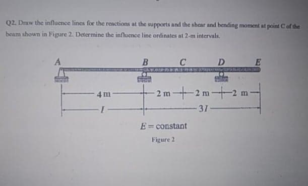
02. Draw the influence lines for the reactions at the supports and the shear and bending moment at point C of the beam shown in Figure 2. Determine the influence line ordinates at 2-m intervals. C D E 2 m -2 m+ 4 m -2 m 31 E= constant %3D Figure 2
Q: 10 kN-m 5 m 5 m
A:
Q: Determine the reactions at A and B if a = 30°. %3D
A:
Q: 4. Solve for the Reactions at B in the Cantilever Beam Shown. 2.25 m 60 KN/m 30 KN/m A 120 KN 75…
A:
Q: (d) MNkN/m 5@2m10m
A:
Q: Draw the F.B.D. for the beam shown in fig and then find the reactions at A and B ? If wo=45 kN/m and…
A:
Q: For the indeterminate beam in figure 7 the ordinates of the influence line fy support reaction Cy…
A: To find : ILD for By and M(E)
Q: 1. Calculate the support reactions at A and C if EI is constant throughout the length. determine the…
A: Given data in question UDL Point load Span member length To find out Reactions FBD
Q: Draw the following influence lines for the beams shown below, 1. Reactions at A, D, and E. 2. Shear…
A:
Q: the beam shown in the figure, draw the influence lines for the reactions MA and RA and the shear and…
A: To draw ILD
Q: Determine the maximum positive moment that can be developed at point D in the beam shown due to a…
A: Given data in question Point load UDL Dead load of beam Span member length To find out Maximum…
Q: Use the Müller–Breslau principle to draw the influence lines for the reactions and internal forces…
A: Solution:- The given figure is shown below,
Q: For the beam shown in the figure, draw the influence lines for the reactions MA and RA and the shear…
A:
Q: 2 kN/m 10 kN 5@2 m = 10 m 5@2 m = 10 m
A:
Q: For the beam shown in Figure ( 2), draw the influence line (I.L) for reaction at E, shear force at…
A: Consider the free body diagram Calculate ILD for reaction at E EE'6=FF'7FF'=1.16716=BB'2BB'=0.33
Q: Draw the detailed influence line for the vertical reactions and moment reactions at supports B, E,…
A: ILD is a graphical representation of variation in reaction, shear force, axial force, deflection…
Q: Calculate for support reactions if: P=55 -Plot shear diagram -Plot moment diagram
A:
Q: 2.2 determine the reactions RA and RB on the beam shown? Z00kN 300 kN.m B
A: Balancing moments and vertical forces
Q: (5) 5 m SN kN-m 3 m
A:
Q: 2m
A: Sign convention used for ILD:Influence line for reaction is positive if the reaction acts upwards.…
Q: Solve for the reactions and draw the shear and moment diagram. (1) 5m FN KN 3 m (2) 5 m MN KN 3 m
A: BMD= BENDING MOMENT DIAGRAM SFD= SHEAR FORCE DIAGRAM
Q: Draw the influence lines for the vertical reactions at the supports and the shear and the bending…
A:
Q: A bridge truss shown in Figure Q1(b) is subjected to a vertical unit load moving trom points D to L.…
A: Answer:-
Q: Draw the influence lines for the horizontal and vertical reactions at supports A and B and the shear…
A: Influence Lines The influence line for a given function those are reaction force, axial force, shear…
Q: D 2m
A: Sign convention used for ILD:Influence line for reaction is positive if the reaction acts upwards.…
Q: 3. Draw the influence lines for the vertical reactions at supports A and E, the reaction moment at…
A: In this question we are asked to draw ILD of given stress functions
Q: (a) 4 m 6 m
A: Given data: Internal hinge at B:
Q: Solve for the reactions and draw the shear and moment diagram. 5 m MN KN 3m
A: Given data MN = 98
Q: (13) 10 kN 5 m 5 m
A:
Q: 2 kips/ft 24 kips 2 kipst C DV B 3 ft 3 t 3ft 3 t
A:
Q: 4 m FN kN/m + 6 m
A: As per bartleby guidelines whenever multiple questions aked by students can be solved first…
Q: Solve for the reactions (in kN) at the hinge and roller support of the overhanging beam shown below.…
A:
Q: Draw influence lines for the reactions at A and C and for the bending moment at E in the beam system…
A: Solution-
Q: For the floor beam system shown in Fig. (3) construct the influence line for: a. the vertical…
A: Given A beam Required Influence line for a. the vertical reaction at B. b. the shear at the left…
Q: For the beam shown in figure below: 1. construct the influence lines and indicate the critical…
A: A unit Load can be Moved from left to Right and Values can be Find Out for Various Components asked…
Q: Draw the influence lines for the vertical reactions at supports B; D, and G and the reaction moment…
A: (Since you have posted a question with multiple sub-parts, we will solve the first three sub-parts…
Q: Influence Lines. , (a) For the determinate beam shown below, draw the Qualitative influence lines…
A: Influence line represents variation in Forces w.r.t Load.
Q: Problem 2: For the beam shown in Figure A. Find the reaction at support B (RB) B. Find the reaction…
A: Given data that,
Q: 2 kN/m 10 kN-m 4 m 6 m 6 m 4 m
A:
Q: I. Solve for the reactions and draw the shear and moment diagram. 101KN/m (d) 5@2 m = 10 m
A:
Q: Determine the moment of the vertical reaction at point A (A,) rotating about the location (XR) of…
A:
Q: Calculate for support reactions if: P=51 -Plot shear diagram -Plot moment diagram
A:
Q: 5@2 m = 10
A:
Q: 1.Determine the Influence Line for the reactions at each support, shear at point C and moment at…
A:
Q: Using the Muller-Breslau Principle, and influence line equations: Sketch the influence lines for…
A:
Q: For the beam shown in the figure, construct the influence lines and compute the maximum values due…
A: The Given information is We have to determine the influence line diagram
Q: اكتب اسمك والتوقيع على الورقة وتهمل اي اجابة بدون الاس و الرسومات الضرورية Draw the F.B.D. for the…
A:
Q: Draw the F.B.D. for the beam shown in fig and then find the reactions at A and B ? If wo= 35 kN/m…
A: given wo = 35 kN/m L= 9 m we have to find RA and RB
Q: C D В А 2 m 4 m 2 m
A: For influence line of shear force at a point on the beam introduce a roller section at that point…
Q: Problem 1 Draw the influence line diagram for the shear and moment at point B and the reaction at…
A: Given data:
Q: (7) 10 kN-m 4 m 6 m
A: Solution:- The given diagram is shown below,
Trending now
This is a popular solution!
Step by step
Solved in 2 steps with 2 images
- In influence line for vertical reactions at support A and the moment at point B of the beams are shown. From the influence line of support A, what is the value of Ay when x = 4.20 m due to a unit load?The horizontal load P can act at any location along the length of member AC shown in Figure P12.26. Draw the influence lines for the moment and shear at section 1, and the moment at section 2.In the figure, draw the influence lines for the reactions Ax and Ay at the left pin support and the bending moment at section 1 located at the face of column AB using ONLY EQUILIBRIUM METHOD. If a uniform live of 0.8 kips/ft is applied on top of the frame, compare the bending moments at section 1 if the live load is only applied on top of the entire span BC, CD, and BD. Discussion the variations and which is the critical loading scenario
- Draw the Influence Line Diagrams for Moment at point D for the beam shownin figure. Plot the values at 1 m intervalDraw the influence lines for bar forces in mem- bers HD and HC of the truss shown in Figure P12.33. The load moves along the bottom chord of the truss. If the truss is to be designed for a uniform live load of 0.32 kip/ft that can be placed anywhere on the span in addition to a concentrated live load of 13 kips that can be positioned where it will produce the largest force, compute the maxi- mum tension and compression forces in bar HD.Draw the influence lines for vertical reactions at supports B and D and the shear and bending moment at point C of the beam shown infigures P8.5, use Muller-Breslau’s Principle. PLEASE REFER TO FIG. P8.5
- (a) Load is applied to the three-hinged trussed arch in Figure P12.40 through the upper chord panel points by a floor beam and stringer floor system. Draw the influence lines for the horizontal and vertical reac- tions at support A and the forces or components of force in members BC, CM, and ML. (b) Assuming that the dead load of the arch and floor system can be represented by a uniform load of 4.8 kips/ft, determine the forces in bars CM and ML produced by the dead load. (c) If the live load is represented by a uniformly distributed load of 0.8 kip/ft of variable length and a concentrated load of 20 kips, determine the maximum force in bar CM produced by the live load. Consider both tension and compression. Joint E acts as a hinge.Draw the influence line for vertical reactions at supports B and D and the shear and bending moment at point C of the beam shown.Draw the influence lines for the vertical reaction at support A, the shear and bending moment at point B of the beam shown below.
- Solve for the maximum moment at B, 4 meters from point A due to a dead load of 5 kn/m a moving live load of 20 kn/m and two movable concentrated load loads 50kn and 75kn 2 meters apart.Draw the influence lines for the shear and bending moment at point F of the beam shown in this figure belowGiven : M1 = 400 kN-m M2 = 500 kN-m M3 = 600 kN-m P = 150 kN w1= 60 kN-m w2 = 120 kN/m a = b = d = 6 m c = 4 m Determine the following: a. The maximum positive shear (in kN). b. The maximum negative shear (in kN). c. The maximum positive moment (in kN-m). d. The maximum negative moment (in kN-m). e. The location of maximum shear from the left end of the beam (in m). f. The location of the maximum moment from the left end of the beam (in m). Kindly Draw the Shear and Moment Diagram. Compute for all of the necessary elements, Include the proper units, use the proper formula and round-off all the answers and final answers to 2 decimal places.