Given : M1 = 400 kN-m M2 = 500 kN-m M3 = 600 kN-m P = 150 kN w1= 60 kN-m w2 = 120 kN/m a = b = d = 6 m c = 4 m Determine the following: a. The maximum positive shear (in kN). b. The maximum negative shear (in kN). c. The maximum positive moment (in kN-m). d. The maximum negative moment (in kN-m). e. The location of maximum shear from the left end of the beam (in m). f. The location of the maximum moment from the left end of the beam (in m). Kindly Draw the Shear and Moment Diagram. Compute for all of the necessary elements, Include the proper units, use the proper formula and round-off all the answers and final answers to 2 decimal places
Given : M1 = 400 kN-m M2 = 500 kN-m M3 = 600 kN-m P = 150 kN w1= 60 kN-m w2 = 120 kN/m a = b = d = 6 m c = 4 m Determine the following: a. The maximum positive shear (in kN). b. The maximum negative shear (in kN). c. The maximum positive moment (in kN-m). d. The maximum negative moment (in kN-m). e. The location of maximum shear from the left end of the beam (in m). f. The location of the maximum moment from the left end of the beam (in m). Kindly Draw the Shear and Moment Diagram. Compute for all of the necessary elements, Include the proper units, use the proper formula and round-off all the answers and final answers to 2 decimal places

Chapter2: Loads On Structures
Section: Chapter Questions
Problem 1P

Related questions

Question
Given :
M1 = 400 kN-m
M2 = 500 kN-m
M3 = 600 kN-m
P = 150 kN
w1= 60 kN-m
w2 = 120 kN/m
a = b = d = 6 m
c = 4 m
Determine the following:
a. The maximum positive shear (in kN).
b. The maximum negative shear (in kN).
c. The maximum positive moment (in kN-m).
d. The maximum negative moment (in kN-m).
e. The location of maximum shear from the left end of the beam (in m).
f. The location of the maximum moment from the left end of the beam (in m).
Kindly Draw the Shear and Moment Diagram. Compute for all of the necessary elements, Include the proper units, use the proper formula and round-off all the answers and final answers to 2 decimal places.
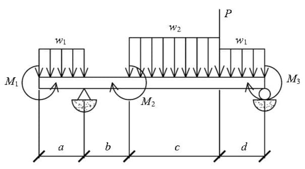
Transcribed Image Text:P
W2
Wi
Wi
M3
M2
a
d
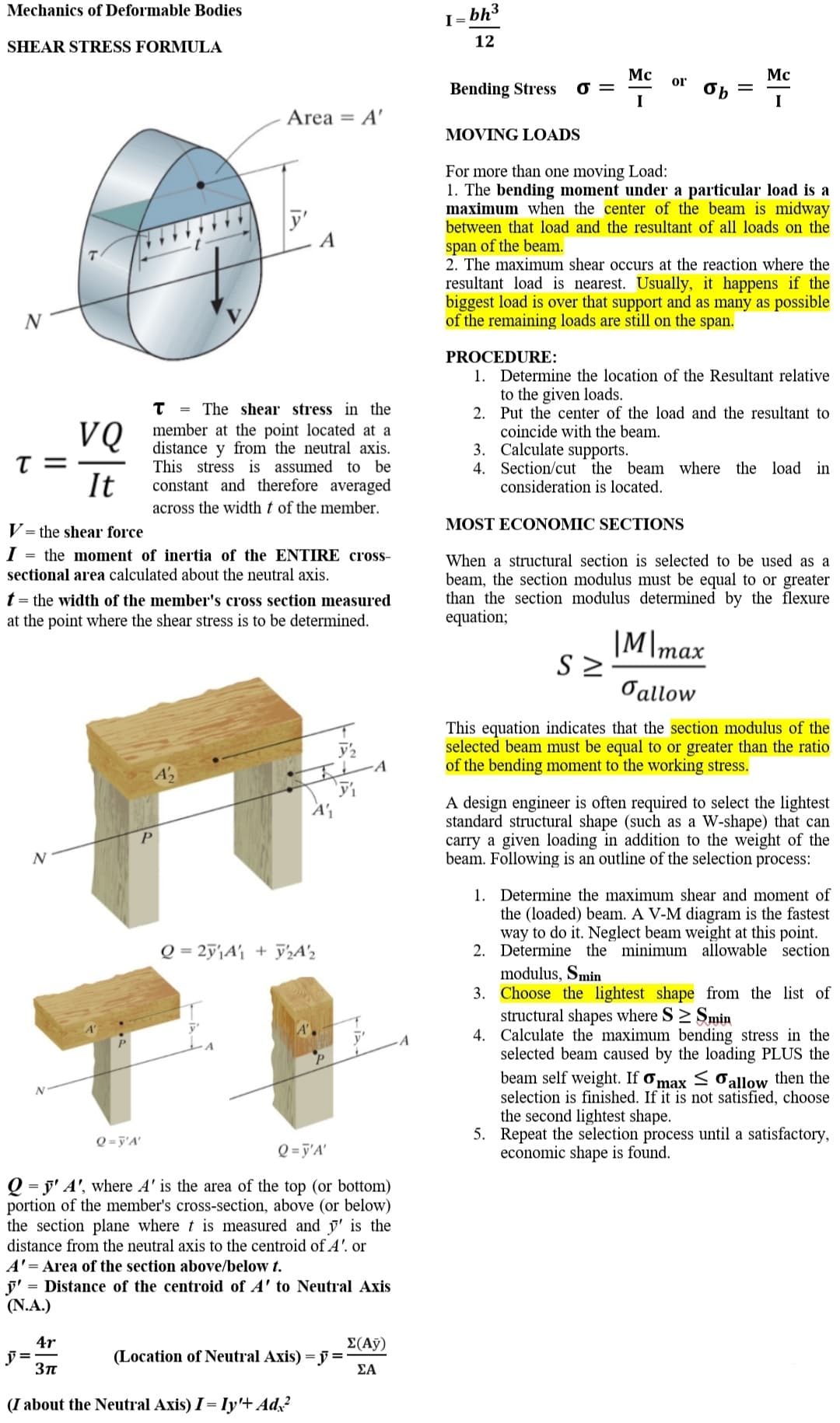
Transcribed Image Text:Mechanics of Deformable Bodies
I =
bh3
SHEAR STRESS FORMULA
12
Mc
Mc
or
Bending Stress
I
I
Area = A'
MOVING LOADS
For more than one moving Load:
1. The bending moment under a particular load is a
maximum when the center of the beam is midway
between that load and the resultant of all loads on the
y'
A
span of the beam.
2. The maximum shear occurs at the reaction where the
resultant load is nearest. Usually, it happens if the
biggest load is over that support and as many as possible
of the remaining loads are still on the span.
PROCEDURE:
1. Determine the location of the Resultant relative
to the given loads.
2. Put the center of the load and the resultant to
coincide with the beam.
3. Calculate supports.
4. Section/cut the beam where the load in
consideration is located.
The shear stress in the
%3D
VQ
T =
It
member at the point located at a
distance
This stress is assumed to be
constant and therefore averaged
y from the neutral axis.
across the width t of the member.
MOST ECONOMIC SECTIONS
V= the shear force
I = the moment of inertia of the ENTIRE cross-
sectional area calculated about the neutral axis.
When a structural section is selected to be used as a
beam, the section modulus must be equal to or greater
than the section modulus determined by the flexure
equation;
t = the width of the member's cross section measured
at the point where the shear stress is to be determined.
|M\max
Oallow
This equation indicates that the section modulus of the
selected beam must be equal to or greater than the ratio
of the bending moment to the working stress.
A design engineer is often required to select the lightest
standard structural shape (such as a W-shape) that can
carry a given loading in addition to the weight of the
beam. Following is an outline of the selection process:
1. Determine the maximum shear and moment of
the (loaded) beam. A V-M diagram is the fastest
way to do it. Neglect beam weight at this point.
2. Determine the minimum allowable section
Q = 2ÿ'\A'j + y½A'½
modulus, Smin
3. Choose the lightest shape from the list of
structural shapes where S> Smin
4. Calculate the maximum bending stress in the
selected beam caused by the loading PLUS the
beam self weight. If ơmax < Oallow then the
selection is finished. If it is not satisfied, choose
the second lightest shape.
5. Repeat the selection process until a satisfactory,
economic shape is found.
Q = j'A'
Q = j'A'
Q = j' A', where A' is the area of the top (or bottom)
portion of the member's cross-section, above (or below)
the section plane where t is measured and y' is the
distance from the neutral axis to the centroid of A'. or
A'= Area of the section above/below t.
j' = Distance of the centroid of A' to Neutral Axis
(N.A.)
4r
E(А)
(Location of Neutral Axis) = y =
ΣΑ
(I about the Neutral Axis) I = Iy'+ Ad,?
Expert Solution
This question has been solved!
Explore an expertly crafted, step-by-step solution for a thorough understanding of key concepts.

Step by step
Solved in 4 steps with 4 images

Knowledge Booster


Learn more about
Need a deep-dive on the concept behind this application? Look no further. Learn more about this topic, civil-engineering and related others by exploring similar questions and additional content below.Recommended textbooks for you

Structural Analysis (10th Edition)
Civil Engineering
ISBN:
9780134610672
Author:
Russell C. Hibbeler
Publisher:
PEARSON

Principles of Foundation Engineering (MindTap Cou…
Civil Engineering
ISBN:
9781337705028
Author:
Braja M. Das, Nagaratnam Sivakugan
Publisher:
Cengage Learning
Structural Analysis (10th Edition)
Civil Engineering
ISBN:
9780134610672
Author:
Russell C. Hibbeler
Publisher:
PEARSON
Principles of Foundation Engineering (MindTap Cou…
Civil Engineering
ISBN:
9781337705028
Author:
Braja M. Das, Nagaratnam Sivakugan
Publisher:
Cengage Learning

Fundamentals of Structural Analysis
Civil Engineering
ISBN:
9780073398006
Author:
Kenneth M. Leet Emeritus, Chia-Ming Uang, Joel Lanning
Publisher:
McGraw-Hill Education


Traffic and Highway Engineering
Civil Engineering
ISBN:
9781305156241
Author:
Garber, Nicholas J.
Publisher:
Cengage Learning