1) A circuit consisting of resistors and capacitors is shown in Fig.-1, below. & = 120.0V, R1 = 4.00 MN, 1) a. R2 = 8.00 M2, R3 = 2.50 MN, R4 = 1.50 MSN, C1 = 15.0 µF, C2 = 10.0 µF, C3 = 7.00 µF, and C4 = 3.50 µF. The switch is initially open, and all capacitors are initially uncharged. b. C. R2 = 8.00 MS2 d. e. R = 4.00 MS2 R3 = 2.50 MS2 R = 1.50 MN C = 15.0 µF C3 = 7.00 µF E= 120.0 V С3%3D 10.0 дF C= 3.50 uF Figure 1 - & = 120.0V, Rị = 4.00 MN, R2 = 8.00 M2, R3 = 2.50 M2, R4 = 1.50 M2, C1 = 15.0 µF, C2 = 10.0 µF, C3 = 7.00 µF, and C4 3.50 µF. a) What will the charge on C4 be 10.0s after the switch is closed? b) What will the potential difference across C4 be 10.0s after the switch is closed? c) What will the current through R4 be 10.0s after the switch is closed? d) What will the potential difference across R4 be 10.0s after the switch is closed? e) The switch remains closed for a long time. But after the capacitors become fully charged, the switch is then opened. What will the charge on C4 be 10.0 s after the switch is opened?
1) A circuit consisting of resistors and capacitors is shown in Fig.-1, below. & = 120.0V, R1 = 4.00 MN, 1) a. R2 = 8.00 M2, R3 = 2.50 MN, R4 = 1.50 MSN, C1 = 15.0 µF, C2 = 10.0 µF, C3 = 7.00 µF, and C4 = 3.50 µF. The switch is initially open, and all capacitors are initially uncharged. b. C. R2 = 8.00 MS2 d. e. R = 4.00 MS2 R3 = 2.50 MS2 R = 1.50 MN C = 15.0 µF C3 = 7.00 µF E= 120.0 V С3%3D 10.0 дF C= 3.50 uF Figure 1 - & = 120.0V, Rị = 4.00 MN, R2 = 8.00 M2, R3 = 2.50 M2, R4 = 1.50 M2, C1 = 15.0 µF, C2 = 10.0 µF, C3 = 7.00 µF, and C4 3.50 µF. a) What will the charge on C4 be 10.0s after the switch is closed? b) What will the potential difference across C4 be 10.0s after the switch is closed? c) What will the current through R4 be 10.0s after the switch is closed? d) What will the potential difference across R4 be 10.0s after the switch is closed? e) The switch remains closed for a long time. But after the capacitors become fully charged, the switch is then opened. What will the charge on C4 be 10.0 s after the switch is opened?

Introductory Circuit Analysis (13th Edition)
13th Edition
ISBN:9780133923605
Author:Robert L. Boylestad
Publisher:Robert L. Boylestad
Chapter1: Introduction
Section: Chapter Questions
Problem 1P: Visit your local library (at school or home) and describe the extent to which it provides literature...

Related questions

Question
Answer as soon as possible!!!!
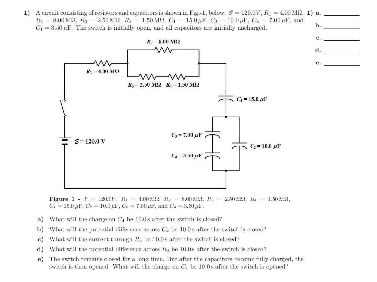
Transcribed Image Text:1) A circuit consisting of resistors and capacitors is shown in Fig.-1, below. & = 120.0V, R1 = 4.00 MN, 1) a.
R2 = 8.00 M2, R3 = 2.50 MN, R4 = 1.50 MSN, C1 = 15.0 µF, C2 = 10.0 µF, C3 = 7.00 µF, and
C4 = 3.50 µF. The switch is initially open, and all capacitors are initially uncharged.
b.
C.
R2 = 8.00 MS2
d.
e.
R = 4.00 MS2
R3 = 2.50 MS2 R = 1.50 MN
C = 15.0 µF
C3 = 7.00 µF
E= 120.0 V
С3%3D 10.0 дF
C= 3.50 uF
Figure 1 - & = 120.0V, Rị = 4.00 MN, R2 = 8.00 M2, R3 = 2.50 M2, R4 = 1.50 M2,
C1 = 15.0 µF, C2 = 10.0 µF, C3 = 7.00 µF, and C4 3.50 µF.
a) What will the charge on C4 be 10.0s after the switch is closed?
b) What will the potential difference across C4 be 10.0s after the switch is closed?
c) What will the current through R4 be 10.0s after the switch is closed?
d) What will the potential difference across R4 be 10.0s after the switch is closed?
e) The switch remains closed for a long time. But after the capacitors become fully charged, the
switch is then opened. What will the charge on C4 be 10.0 s after the switch is opened?
Expert Solution


Trending now
This is a popular solution!

Step by step
Solved in 9 steps with 8 images

Knowledge Booster


Learn more about
Need a deep-dive on the concept behind this application? Look no further. Learn more about this topic, electrical-engineering and related others by exploring similar questions and additional content below.Recommended textbooks for you
Introductory Circuit Analysis (13th Edition)
Electrical Engineering
ISBN:
9780133923605
Author:
Robert L. Boylestad
Publisher:
PEARSON

Delmar's Standard Textbook Of Electricity
Electrical Engineering
ISBN:
9781337900348
Author:
Stephen L. Herman
Publisher:
Cengage Learning

Programmable Logic Controllers
Electrical Engineering
ISBN:
9780073373843
Author:
Frank D. Petruzella
Publisher:
McGraw-Hill Education
Introductory Circuit Analysis (13th Edition)
Electrical Engineering
ISBN:
9780133923605
Author:
Robert L. Boylestad
Publisher:
PEARSON
Delmar's Standard Textbook Of Electricity
Electrical Engineering
ISBN:
9781337900348
Author:
Stephen L. Herman
Publisher:
Cengage Learning
Programmable Logic Controllers
Electrical Engineering
ISBN:
9780073373843
Author:
Frank D. Petruzella
Publisher:
McGraw-Hill Education

Fundamentals of Electric Circuits
Electrical Engineering
ISBN:
9780078028229
Author:
Charles K Alexander, Matthew Sadiku
Publisher:
McGraw-Hill Education

Electric Circuits. (11th Edition)
Electrical Engineering
ISBN:
9780134746968
Author:
James W. Nilsson, Susan Riedel
Publisher:
PEARSON

Engineering Electromagnetics
Electrical Engineering
ISBN:
9780078028151
Author:
Hayt, William H. (william Hart), Jr, BUCK, John A.
Publisher:
Mcgraw-hill Education,