1- The impedance of a capacitor increases with increasing frequency. (a) True (b) False 2- If the load impedance is 20-j20, the power factor is (a)-45 (e) none of these (b) 0 (d) (d) 3- A series RL circuit has VR = 10 V and VL = 6 V. The supply voltage is: (c) 1 (c) 1 0.7071 0.7071 (a) -4 V (b) 4 V (c) 11.66 V (d) 16 V 4- In the power triangle (a) 1000 VAR leading (c) 866 VAR leading shown in Fig.1(a), the reactive power is: (b) 1000 VAR lagging (d) 866 VAR lagging 5- For the power triangle in Fig.1(b), the apparent power is: (a) 2000 VA (c) 866 VAR (b) 1000 VAR (d) 500 VAR 60° 500 W (ə) 30° (b) 1000 V
1- The impedance of a capacitor increases with increasing frequency. (a) True (b) False 2- If the load impedance is 20-j20, the power factor is (a)-45 (e) none of these (b) 0 (d) (d) 3- A series RL circuit has VR = 10 V and VL = 6 V. The supply voltage is: (c) 1 (c) 1 0.7071 0.7071 (a) -4 V (b) 4 V (c) 11.66 V (d) 16 V 4- In the power triangle (a) 1000 VAR leading (c) 866 VAR leading shown in Fig.1(a), the reactive power is: (b) 1000 VAR lagging (d) 866 VAR lagging 5- For the power triangle in Fig.1(b), the apparent power is: (a) 2000 VA (c) 866 VAR (b) 1000 VAR (d) 500 VAR 60° 500 W (ə) 30° (b) 1000 V

Introductory Circuit Analysis (13th Edition)
13th Edition
ISBN:9780133923605
Author:Robert L. Boylestad
Publisher:Robert L. Boylestad
Chapter1: Introduction
Section: Chapter Questions
Problem 1P: Visit your local library (at school or home) and describe the extent to which it provides literature...

Related questions
Question
Transcribed Image Text:1- The impedance of a capacitor increases with increasing frequency.
(a) True (b) False
2- If the load impedance is 20-j20, the power factor is
(a) -45° (b) 0 (c) 1
(d) 0.7071
(e) none of these
3- A series RL circuit has VR = 10 V and VL = 6 V. The supply voltage is:
(a) -4 V (b) 4 V (c) 11.66 V (d) 16 V
is:
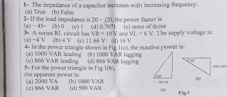
4- In the power triangle shown in Fig. 1(a), the reactive power
(a) 1000 VAR leading
(c) 866 VAR leading
(b) 1000 VAR lagging
(d) 866 VAR lagging
5- For the power triangle in Fig.1(b),
the apparent power is:
(a) 2000 VA
(c) 866 VAR
(b) 1000 VAR
(d) 500 VAR
60⁰
500 W
(a)
Fig.1
30⁰
(b)
1000 VAR
Expert Solution
This question has been solved!
Explore an expertly crafted, step-by-step solution for a thorough understanding of key concepts.

Step by step
Solved in 6 steps with 5 images

Knowledge Booster


Learn more about
Need a deep-dive on the concept behind this application? Look no further. Learn more about this topic, electrical-engineering and related others by exploring similar questions and additional content below.Recommended textbooks for you
Introductory Circuit Analysis (13th Edition)
Electrical Engineering
ISBN:
9780133923605
Author:
Robert L. Boylestad
Publisher:
PEARSON

Delmar's Standard Textbook Of Electricity
Electrical Engineering
ISBN:
9781337900348
Author:
Stephen L. Herman
Publisher:
Cengage Learning

Programmable Logic Controllers
Electrical Engineering
ISBN:
9780073373843
Author:
Frank D. Petruzella
Publisher:
McGraw-Hill Education
Introductory Circuit Analysis (13th Edition)
Electrical Engineering
ISBN:
9780133923605
Author:
Robert L. Boylestad
Publisher:
PEARSON
Delmar's Standard Textbook Of Electricity
Electrical Engineering
ISBN:
9781337900348
Author:
Stephen L. Herman
Publisher:
Cengage Learning
Programmable Logic Controllers
Electrical Engineering
ISBN:
9780073373843
Author:
Frank D. Petruzella
Publisher:
McGraw-Hill Education

Fundamentals of Electric Circuits
Electrical Engineering
ISBN:
9780078028229
Author:
Charles K Alexander, Matthew Sadiku
Publisher:
McGraw-Hill Education

Electric Circuits. (11th Edition)
Electrical Engineering
ISBN:
9780134746968
Author:
James W. Nilsson, Susan Riedel
Publisher:
PEARSON

Engineering Electromagnetics
Electrical Engineering
ISBN:
9780078028151
Author:
Hayt, William H. (william Hart), Jr, BUCK, John A.
Publisher:
Mcgraw-hill Education,