Ε1 + I b ww R₁ = 2.2 k E2 I d R₂ = 3.3 ΚΩ lx R3 = 2.0 ΚΩ W Vx Figure 3.0: Circuit with multiple voltage sources
Ε1 + I b ww R₁ = 2.2 k E2 I d R₂ = 3.3 ΚΩ lx R3 = 2.0 ΚΩ W Vx Figure 3.0: Circuit with multiple voltage sources

Introductory Circuit Analysis (13th Edition)
13th Edition
ISBN:9780133923605
Author:Robert L. Boylestad
Publisher:Robert L. Boylestad
Chapter1: Introduction
Section: Chapter Questions
Problem 1P: Visit your local library (at school or home) and describe the extent to which it provides literature...

Related questions

Question
100%
Please answer parts (i) and (ii) and include all calculations and steps, thank you so much!
Transcribed Image Text:Vx
(volts)
Th.
MS.
Ix
(mA)
Th.
E₁
MS.
+
b
R₁ = 2.2 k
Th.
Vx1
(volts)
E₂
MS.
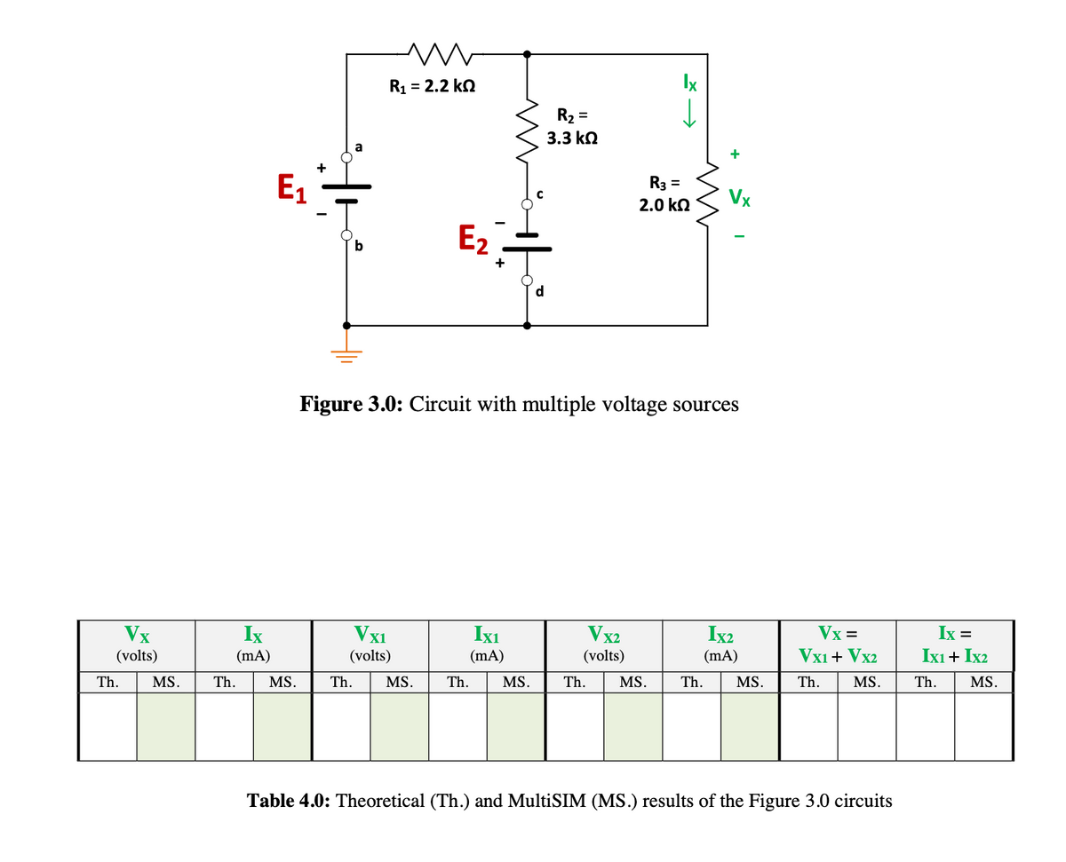
Figure 3.0: Circuit with multiple voltage sources
Th.
F
R₂ =
3.3 ΚΩ
Ixı
(mA)
MS.
Vx2
(volts)
R3 =
2.0 ΚΩ
Th.
MS.
Th.
Ix2
(mA)
MS.
Vx=
VX1 + Vx2
Th. MS.
Table 4.0: Theoretical (Th.) and MultiSIM (MS.) results of the Figure 3.0 circuits
Ix =
IX1 + IX2
Th.
MS.
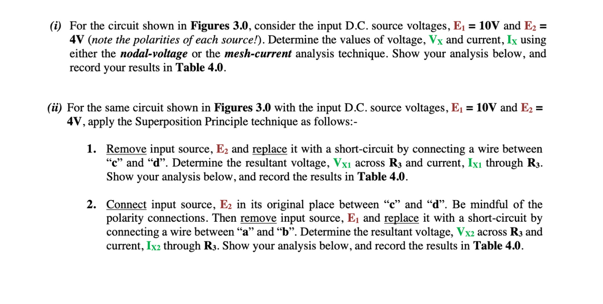
Transcribed Image Text:(i) For the circuit shown in Figures 3.0, consider the input D.C. source voltages, E₁ = 10V and E₂ =
4V (note the polarities of each source!). Determine the values of voltage, Vx and current, Ix using
either the nodal-voltage or the mesh-current analysis technique. Show your analysis below, and
record your results in Table 4.0.
(ii) For the same circuit shown in Figures 3.0 with the input D.C. source voltages, E₁ = 10V and E₂ =
4V, apply the Superposition Principle technique as follows:-
1.
Remove input source, E₂ and replace it with a short-circuit by connecting a wire between
"c" and "d". Determine the resultant voltage, Vx₁ across R3 and current, Ix₁ through R3.
Show your analysis below, and record the results in Table 4.0.
2. Connect input source, E2 in its original place between "c" and "d". Be mindful of the
polarity connections. Then remove input source, E₁ and replace it with a short-circuit by
connecting a wire between "a" and "b". Determine the resultant voltage, Vx2 across R3 and
current, Ix2 through R3. Show your analysis below, and record the results in Table 4.0.
Expert Solution
This question has been solved!
Explore an expertly crafted, step-by-step solution for a thorough understanding of key concepts.

Step by step
Solved in 3 steps with 32 images

Knowledge Booster


Learn more about
Need a deep-dive on the concept behind this application? Look no further. Learn more about this topic, electrical-engineering and related others by exploring similar questions and additional content below.Recommended textbooks for you
Introductory Circuit Analysis (13th Edition)
Electrical Engineering
ISBN:
9780133923605
Author:
Robert L. Boylestad
Publisher:
PEARSON

Delmar's Standard Textbook Of Electricity
Electrical Engineering
ISBN:
9781337900348
Author:
Stephen L. Herman
Publisher:
Cengage Learning

Programmable Logic Controllers
Electrical Engineering
ISBN:
9780073373843
Author:
Frank D. Petruzella
Publisher:
McGraw-Hill Education
Introductory Circuit Analysis (13th Edition)
Electrical Engineering
ISBN:
9780133923605
Author:
Robert L. Boylestad
Publisher:
PEARSON
Delmar's Standard Textbook Of Electricity
Electrical Engineering
ISBN:
9781337900348
Author:
Stephen L. Herman
Publisher:
Cengage Learning
Programmable Logic Controllers
Electrical Engineering
ISBN:
9780073373843
Author:
Frank D. Petruzella
Publisher:
McGraw-Hill Education

Fundamentals of Electric Circuits
Electrical Engineering
ISBN:
9780078028229
Author:
Charles K Alexander, Matthew Sadiku
Publisher:
McGraw-Hill Education

Electric Circuits. (11th Edition)
Electrical Engineering
ISBN:
9780134746968
Author:
James W. Nilsson, Susan Riedel
Publisher:
PEARSON

Engineering Electromagnetics
Electrical Engineering
ISBN:
9780078028151
Author:
Hayt, William H. (william Hart), Jr, BUCK, John A.
Publisher:
Mcgraw-hill Education,