1) You will be building an RLC circuit. However, the only inductor (L = 175 mH) and resistor (R = 232 Q) %3D you have are currently in a DC LR circuit. To safely remove the components from the DC circuit you must wait for the current to leave the inductor AFTER battery is removed. a. If the inductor starts out fully "charged", how long will it take for the current to drop down to 5% of the starting/maximum current? NOTE: The value of the starting/maximum current is not needed! The inductor, resistor, and a capacitor (C = 4.8 µF) are now combined with an AC voltage source to form a driven LRC circuit in a single loop. The voltage source runs at frequency of 275.3 Hz (this if “f" not “w"!). b. Determine the total impedence for the circuit. С. Determine the phase for the circuit. d. An RMS current of 1.61 A is found. Create a phasor diagram including all voltages for all components (Vsource, Vr, Vi, and Vc). If the frequency of the voltage source is doubled, determine if and how the voltage of each е. device (Vsource, Vr, V, and Vc) would change and WHY. No calculations are needed here, I am се, just look for something like: "It gets bigger", “It gets smaller", or “It doesn't change". Do not forget about the WHY!
1) You will be building an RLC circuit. However, the only inductor (L = 175 mH) and resistor (R = 232 Q) %3D you have are currently in a DC LR circuit. To safely remove the components from the DC circuit you must wait for the current to leave the inductor AFTER battery is removed. a. If the inductor starts out fully "charged", how long will it take for the current to drop down to 5% of the starting/maximum current? NOTE: The value of the starting/maximum current is not needed! The inductor, resistor, and a capacitor (C = 4.8 µF) are now combined with an AC voltage source to form a driven LRC circuit in a single loop. The voltage source runs at frequency of 275.3 Hz (this if “f" not “w"!). b. Determine the total impedence for the circuit. С. Determine the phase for the circuit. d. An RMS current of 1.61 A is found. Create a phasor diagram including all voltages for all components (Vsource, Vr, Vi, and Vc). If the frequency of the voltage source is doubled, determine if and how the voltage of each е. device (Vsource, Vr, V, and Vc) would change and WHY. No calculations are needed here, I am се, just look for something like: "It gets bigger", “It gets smaller", or “It doesn't change". Do not forget about the WHY!

Introductory Circuit Analysis (13th Edition)
13th Edition
ISBN:9780133923605
Author:Robert L. Boylestad
Publisher:Robert L. Boylestad
Chapter1: Introduction
Section: Chapter Questions
Problem 1P: Visit your local library (at school or home) and describe the extent to which it provides literature...

Related questions

Question
please solve A-E
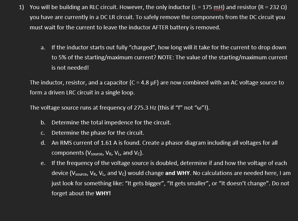
Transcribed Image Text:1) You will be building an RLC circuit. However, the only inductor (L = 175 mH) and resistor (R = 232 Q)
you have are currently in a DC LR circuit. To safely remove the components from the DC circuit you
must wait for the current to leave the inductor AFTER battery is removed.
а.
If the inductor starts out fully "charged", how long will it take for the current to drop down
to 5% of the starting/maximum current? NOTE: The value of the starting/maximum current
is not needed!
The inductor, resistor, and a capacitor (C = 4.8 µF) are now combined with an AC voltage source to
form a driven LRC circuit in a single loop.
The voltage source runs at frequency of 275.3 Hz (this if "f" not "w"!).
b. Determine the total impedence for the circuit.
С.
Determine the phase for the circuit.
d. An RMS current of 1.61 A is found. Create a phasor diagram including all voltages for all
components (Vsource, VR, VL, and Vc).
e. If the frequency of the voltage source is doubled, determine if and how the voltage of each
device (Vsource, VR, VL, and Vc) would change and WHY. No calculations are needed here, I am
just look for something like: "It gets bigger", "It gets smaller", or "It doesn't change". Do not
forget about the WHY!
Expert Solution
This question has been solved!
Explore an expertly crafted, step-by-step solution for a thorough understanding of key concepts.

Step by step
Solved in 10 steps with 4 images

Knowledge Booster


Learn more about
Need a deep-dive on the concept behind this application? Look no further. Learn more about this topic, electrical-engineering and related others by exploring similar questions and additional content below.Recommended textbooks for you
Introductory Circuit Analysis (13th Edition)
Electrical Engineering
ISBN:
9780133923605
Author:
Robert L. Boylestad
Publisher:
PEARSON

Delmar's Standard Textbook Of Electricity
Electrical Engineering
ISBN:
9781337900348
Author:
Stephen L. Herman
Publisher:
Cengage Learning

Programmable Logic Controllers
Electrical Engineering
ISBN:
9780073373843
Author:
Frank D. Petruzella
Publisher:
McGraw-Hill Education
Introductory Circuit Analysis (13th Edition)
Electrical Engineering
ISBN:
9780133923605
Author:
Robert L. Boylestad
Publisher:
PEARSON
Delmar's Standard Textbook Of Electricity
Electrical Engineering
ISBN:
9781337900348
Author:
Stephen L. Herman
Publisher:
Cengage Learning
Programmable Logic Controllers
Electrical Engineering
ISBN:
9780073373843
Author:
Frank D. Petruzella
Publisher:
McGraw-Hill Education

Fundamentals of Electric Circuits
Electrical Engineering
ISBN:
9780078028229
Author:
Charles K Alexander, Matthew Sadiku
Publisher:
McGraw-Hill Education

Electric Circuits. (11th Edition)
Electrical Engineering
ISBN:
9780134746968
Author:
James W. Nilsson, Susan Riedel
Publisher:
PEARSON

Engineering Electromagnetics
Electrical Engineering
ISBN:
9780078028151
Author:
Hayt, William H. (william Hart), Jr, BUCK, John A.
Publisher:
Mcgraw-hill Education,