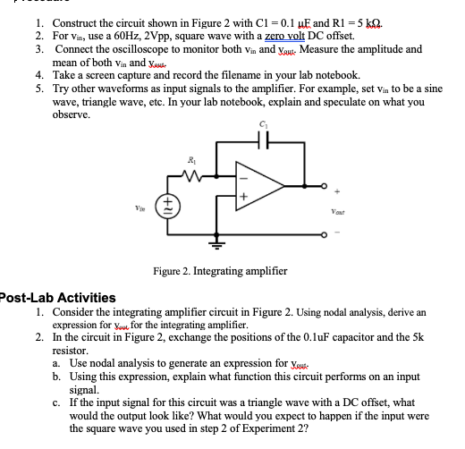
1. Construct the circuit shown in Figure 2 with C1 = 0.1 µE and R1 = 5 kQ. 2. For vin, use a 60HZ, 2Vpp, square wave with a zero volt DC offset. 3. Connect the oscilloscope to monitor both Vin and ygu Measure the amplitude and mean of both vin and yaude 4. Take a screen capture and record the filename in your lab notebook. 5. Try other waveforms as input signals to the amplifier. For example, set vin to be a sine wave, triangle wave, etc. In your lab notebook, explain and speculate on what you observe. Vant Figure 2. Integrating amplifier Post-Lab Activities 1. Consider the integrating amplifier circuit in Figure 2. Using nodal analysis, derive an expression for vou, for the integrating amplifier. 2. In the circuit in Figure 2, exchange the positions of the 0.luF capacitor and the 5k resistor. a. Use nodal analysis to generate an expression for ygus- b. Using this expression, explain what function this circuit performs on an input signal. c. If the input signal for this circuit was a triangle wave with a DC offset, what would the output look like? What would you expect to happen if the input were the square wave you used in step 2 of Experiment 2?


Power Amplifier
The power amplifier is an electronic amplifier designed to maximize the signal strength of a given input. The input signal strength is enhanced to a high enough level to drive output devices such as speakers, headphones, RF (Radio frequency) transmitters, etc. Unlike voltage / current amplifiers, the power amplifier is designed to drive core loads directly and is used as a storage block in the amplifier series.
Maximum Efficiency Criterion
In every field of engineering, there is a tremendous use of the machine and all those machines are equipped for their popular work efficiency so it very much important for operation engineers to monitor the efficiency of the machine, planning engineers to check out the efficiency of the machine before installing the machine and design engineers to design machine for higher efficiency than and then the utility will procure their products that will ultimately lead to profit and loss of the company. It indicates the importance of efficiency right from the initial stage as manufacturing units, intermediate stage as planning coordinators, and end-users stage as a utility.
- Consider the integrating amplifier circuit in Figure 2. Using nodal analysis, derive an expression for vout for the integrating amplifier.
-
In the circuit in Figure 2, exchange the positions of the 0.1uF capacitor and the 5k resistor.a. Use nodal analysis to generate an expression for vout.b. Using this expression, explain what function this circuit performs on an input signal.


Trending now
This is a popular solution!

Step by step
Solved in 3 steps with 4 images


