1. Illustrate a wiring connection diagram of a simple AVR circuit. Refer to the example in Figure 1. 2. Illustrate a logic diagram of a KVM switch based on the following truth table. Refer to the example in Figure 2. KVM Switch Comp. Unit 1 Comp. Unit 2 Comp. Unit 3 Switch A 1 0 0 Switch B 0 1 0 Switch C 0 0 1
1. Illustrate a wiring connection diagram of a simple AVR circuit. Refer to the example in Figure 1. 2. Illustrate a logic diagram of a KVM switch based on the following truth table. Refer to the example in Figure 2. KVM Switch Comp. Unit 1 Comp. Unit 2 Comp. Unit 3 Switch A 1 0 0 Switch B 0 1 0 Switch C 0 0 1

Power System Analysis and Design (MindTap Course List)
6th Edition
ISBN:9781305632134
Author:J. Duncan Glover, Thomas Overbye, Mulukutla S. Sarma
Publisher:J. Duncan Glover, Thomas Overbye, Mulukutla S. Sarma
Chapter2: Fundamentals
Section: Chapter Questions
Problem 2.39P

Related questions

Question
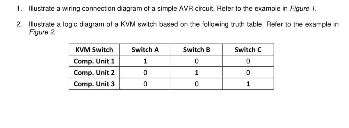
Transcribed Image Text:1. Illustrate a wiring connection diagram of a simple AVR circuit. Refer to the example in Figure 1.
2. Illustrate a logic diagram of a KVM switch based on the following truth table. Refer to the example in
Figure 2.
KVM Switch
Comp. Unit 1
Comp. Unit 2
Comp. Unit 3
Switch A
1
0
0
Switch B
0
1
0
Switch C
0
0
1
Transcribed Image Text:230V or
120V AC
b0
a0
bl
al
62
a2
b3
a3
Fuse
Two Pole
Switch
Battery
12V DC
UPS/Inverter
OUTPUT
230V or 120V AC
INPUT
230V
or
120V AC
ml
m2
ON
m3
용
3
OFF
ON
OFF
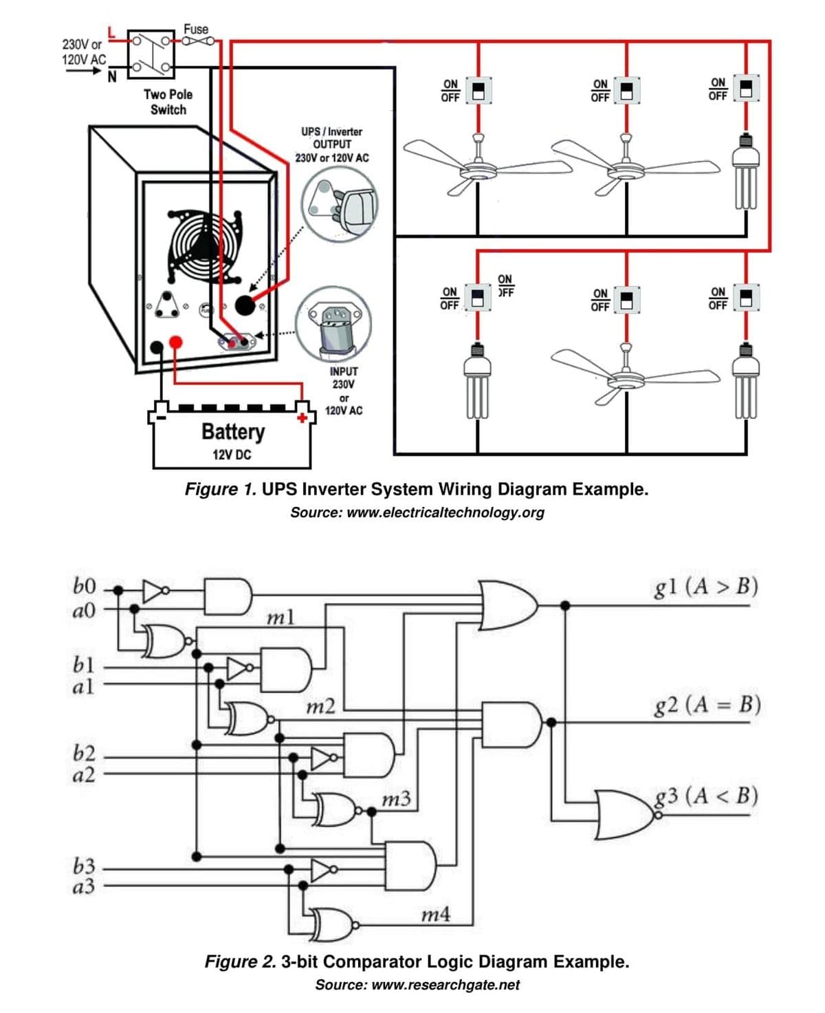
Figure 1. UPS Inverter System Wiring Diagram Example.
Source: www.electricaltechnology.org
m4
ON
OFF
ON
OFF
I
Figure 2. 3-bit Comparator Logic Diagram Example.
Source: www.researchgate.net
ON
OFF
ON
OFF
gl (A > B)
g2 (A= B)
g3 (A <B)
Expert Solution
This question has been solved!
Explore an expertly crafted, step-by-step solution for a thorough understanding of key concepts.

This is a popular solution!

Trending now
This is a popular solution!

Step by step
Solved in 2 steps

Knowledge Booster


Learn more about
Need a deep-dive on the concept behind this application? Look no further. Learn more about this topic, electrical-engineering and related others by exploring similar questions and additional content below.Recommended textbooks for you
Power System Analysis and Design (MindTap Course …
Electrical Engineering
ISBN:
9781305632134
Author:
J. Duncan Glover, Thomas Overbye, Mulukutla S. Sarma
Publisher:
Cengage Learning
Power System Analysis and Design (MindTap Course …
Electrical Engineering
ISBN:
9781305632134
Author:
J. Duncan Glover, Thomas Overbye, Mulukutla S. Sarma
Publisher:
Cengage Learning